TOPICAL REVIEW
A review of power harvesting using piezoelectric materials (2003–2006)
Steven R Anton1 and Henry A Sodano2
1 Center for Intelligent Material Systems and Structures, Virginia Polytechnic Institute and State University, Blacksburg, VA 24061-0261, USA 2 Department of Mechanical Engineering—Engineering Mechanics, Michigan Technological University, Houghton, MI 49931-1295, USA
E-mail: sranton@vt.edu
Received 23 August 2006, in final form 11 January 2007
Published 18 May 2007
Online at stacks.iop.org/SMS/16/R1
Abstract
The field of power harvesting has experienced significant growth over the past few years due to the ever-increasing desire to produce portable and wireless electronics with extended lifespans. Current portable and wireless devices must be designed to include electrochemical batteries as the power source. The use of batteries can be troublesome due to their limited lifespan, thus necessitating their periodic replacement. In the case of wireless sensors that are to be placed in remote locations, the sensor must be easily accessible or of a disposable nature to allow the device to function over extended periods of time. Energy scavenging devices are designed to capture the ambient energy surrounding the electronics and convert it into usable electrical energy. The concept of power harvesting works towards developing self-powered devices that do not require replaceable power supplies. A number of sources of harvestable ambient energy exist, including waste heat, vibration, electromagnetic waves, wind, flowing water, and solar energy. While each of these sources of energy can be effectively used to power remote sensors, the structural and biological communities have placed an emphasis on scavenging vibrational energy with piezoelectric materials. This article will review recent literature in the field of power harvesting and present the current state of power harvesting in its drive to create completely self-powered devices.
(Some figures in this article are in colour only in the electronic version)
1. Introduction
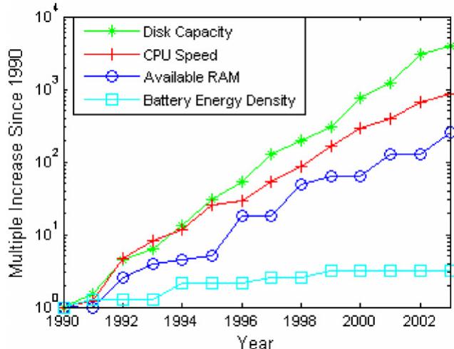
Over the past few decades the use of wireless sensors and wearable electronics has grown steadily. These electronics have all relied on the use of electrochemical batteries for providing electrical energy to the device. The growth of battery technology, however, has remained relatively stagnant over the past decade while the performance of computing systems has grown steadily, as shown in figure 1. The advancement in computing performance has also led to increased power usage from the electronics, which in the case of CMOS technology follows a linear increase in power with respect to computing speed. The increase in power used by the electronics has led to a reduction in battery life and has limited the functionality of the devices. In an effort to extend the life and reduce the volume of the electronics, researchers have begun investigating methods of obtaining electrical energy from the ambient energy surrounding the device.
Many environments are subjected to ambient vibration energy that commonly goes unused. Several methods exist for obtaining electrical energy from this source including the use of electromagnetic induction (for instance, see
line chart
| Year | Disk Capacity | CPU Speed | Available RAM | Battery Energy Density |
|---|---|---|---|---|
| 1990 | 1 | 1 | 1 | 1 |
| 1992 | 5 | 5 | 3 | 1 |
| 1994 | 10 | 10 | 5 | 2 |
| 1996 | 50 | 50 | 15 | 2 |
| 1998 | 200 | 150 | 50 | 3 |
| 2000 | 1000 | 500 | 100 | 3 |
| 2002 | 5000 | 2000 | 200 | 3 |
| 2004 | 10000 | 5000 | 500 | 3 |
Figure 1. Advances in computer and battery technology since 1990. (Derived from data in Paradiso and Starner 2005.)
Glynne-Jones et al 2004), electrostatic generation (for instance, see Mitcheson et al 2004), dielectric elastomers (for instance, see Kornbluh et al 2002), and piezoelectric materials. While each of the aforementioned techniques can provide a useful amount of energy, piezoelectric materials have received the most attention due to their ability to directly convert applied strain energy into usable electric energy and the ease at which they can be integrated into a system. This energy conversion occurs because the piezoelectric molecular structure is oriented such that the material exhibits a local charge separation, known as an electric dipole. When strain energy is applied to the material it results in a deformation of the dipole and the formation of a charge that can be removed from the material and used to power various devices.
The strain-dependent charge output of piezoelectric materials has typically been used for sensor applications and can be found in a variety of different devices including accelerometers, microphones, load cells, etc. More recently, the concept of shunt damping was developed, in which the electrical output of the piezoelectric material is used for damping purposes rather than sensing (Lesieutre 1998). Because a portion of the vibration energy is converted to electrical energy by the piezoelectric material, when it is dissipated through Joule heating, energy is removed from the system resulting in a damping effect. The concept behind shunt damping is also used in power harvesting; however, rather than dissipating the energy it is used to power some other device.
The rapid growth of research being performed in the field of power harvesting has resulted in significant improvements to various energy scavenging techniques. This article will present a review of the recent advances in power harvesting using piezoelectric materials since Sodano et al (2004b) published a review of the field in 2004, which the reader is referred to as an introduction. This article will cover various topics in power harvesting using piezoelectric materials, including the design of efficient harvesting geometries, improving efficiency through circuitry, implantable and wearable power supplies, harvesting of ambient flows, microelectromechanical devices, self-powered sensors and comparisons of piezoelectric materials to other energy harvesting media.
2. Improving efficiency and power generation through piezoelectric configurations
Piezoelectric materials can be configured in many different ways that prove useful in power harvesting applications. The configuration of the power harvesting device can be changed through modification of piezoelectric materials, altering the electrode pattern, changing the poling and stress direction, layering the material to maximize the active volume, adding prestress to maximize the coupling and applied strain of the material, and tuning the resonant frequency of the device. A large percentage of recent research in power harvesting with piezoelectric materials has focused on improving the efficiency of piezoelectric power harvesting systems. The following articles have all investigated ways to improve the efficiency of power harvesting by altering the configuration of the piezoelectric device in order to maximize the energy extracted from the ambient source. A review of these studies presents a wide variety of unique configurations, each of which proves to be advantageous under certain circumstances.
The type of piezoelectric material selected for a power harvesting application can have a major influence on the harvester’s functionality and performance. To date, a number of different piezoelectric materials have been developed. The most common type of piezoelectric used in power harvesting applications is lead zirconate titanate, a piezoelectric ceramic, or piezoceramic, known as PZT. Although PZT is widely used as a power harvesting material, the piezoceramic’s extremely brittle nature causes limitations in the strain that it can safely absorb without being damaged. Lee et al (2005) note that piezoceramics are susceptible to fatigue crack growth when subjected to high frequency cyclic loading. In order to eliminate the disadvantages of piezoceramic materials and improve upon their efficiency, researchers have developed and tested other, more flexible, piezoelectric materials that can be used in energy harvesting applications.
Another common piezoelectric material is poly(vinylidene fluoride) (PVDF). PVDF is a piezoelectric polymer that exhibits considerable flexibility when compared to PZT. Lee et al (2004, 2005) developed a PVDF film that was coated with poly(3,4-ethylenedioxy-thiophene)/poly(4- styrenesulfonate) [PEDOT/PSS] electrodes. They compared the PEDOT/PSS coated films to films coated with the inorganic electrode materials, indium tin oxide (ITO) and platinum (Pt). When subjected to vibrations of the same magnitude over varying frequencies, it was found that the films with Pt electrodes began to show fatigue crack damage of the electrode surface at a frequency of 33 kHz. The ITO electrodes became damaged when operating at a frequency of 213 Hz. The PEDOT/PSS film, however, ran for 10 h at 1 MHz without electrode damage. One can conclude that, by utilizing a more durable electrode layer, a piezoelectric device can operate under more strenuous conditions. This may give the device the ability to harvest more power throughout its lifespan; however, the exact effect of a stronger electrode layer may vary depending on the specific application.
Mohammadi et al (2003) developed a fiber-based piezoelectric (piezofiber) material consisting of PZT fibers of various diameters (15, 45, 120, and 250 μm) that were aligned, laminated, and molded in an epoxy (Bent et al 1995).
text_image
Cylindrical Piezoelectric fibers in epoxy matrix Interdigitated electrode (IDE) pattern t/b on Kapton film (film not shown) Epoxy matrix IDE electric field directed primarily in fiber axis (1-direction) IDE used to pole piezoelectric material alternately along 1-direction section through 1-3 plane
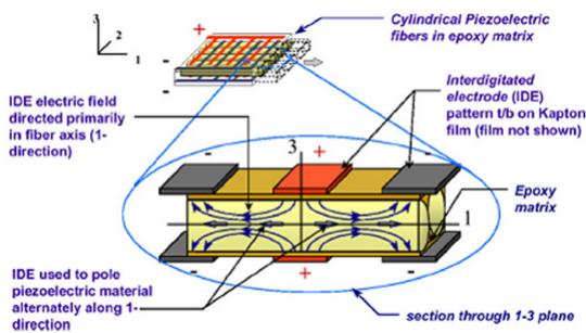
Figure 2. Schematic of the cross section of an active fiber composite (AFC) actuator. (Figure from Wilkie et al 2000.)
This resulted in flexible composites with 40% of the volume consisting of aligned piezoelectric fibers and the remaining 60% made up of epoxy. Several samples were made in which several 34 mm × 11 mm rectangular plates of various thicknesses (1.2–5.8 mm) were diced from the composite such that the fibers were oriented in the plate thickness direction. The voltage output of the samples was tested by dropping a 33.5 g, 20 mm diameter stainless steel ball on them from a height of 10 cm. The peak power was also calculated considering a 1 M- load resistance. A maximum voltage and power output of 350 V and 120 mW was obtained for the thickest transducer, 5.85 mm thick, with the smallest fiber diameter, 15 μm. Upon studying the relationship between voltage output of the harvester and its physical geometry, it was determined that thicker plates have the capability of larger fiber displacements, and that samples with smaller diameter fibers have the highest piezoelectric coefficient, and lowest dielectric constant defined in this study as , both of which contribute towards higher power outputs and more efficient systems.
Piezofiber power harvesting materials have also been investigated by Churchill et al (2003) who tested a composite consisting of unidirectionally aligned PZT fibers of 250 μm diameter embedded in a resin matrix. It was found that when a 0.38 mm thick sample of 130 mm length and 13 mm width was subjected to a 180 Hz vibration that caused a strain of 300 in the sample, the composite was able to harvest about 7.5 mW of power. The results of this study show that a relatively small fiber-based piezoelectric power harvester can supply useable amounts of power from cyclic strain vibration in the local environment.
Sodano et al (2004a) presented a comparison of several piezoelectric composite devices for power harvesting that are normally used for sensing and actuation. The power harvesting ability of the macro-fiber composite (MFC), quick pack IDE (model QP10ni), and the quick pack model (QP10n) actuators was tested. The MFC contains piezofibers embedded in an epoxy matrix which affords it extreme flexibility, and it utilizes interdigitated electrodes, which allow the electric field to be applied along the length of the fiber and act in the higher coupling mode, as shown in figure 2. A detailed explanation of the operation and of various applications of MFC devices is presented by Sch¨onecker et al (2006). The quick pack IDE contains interdigitated electrodes but conventional monolithic piezoceramic material, and the quick pack simply uses a traditional electrode pattern and a monolithic piezoceramic.
To experimentally compare the efficiencies of these materials, all three were mounted to the same cantilever beam and thus subjected to the same vibration input. Tests were run at the first 12 vibration modes of the beam and the power output, which was normalized to volume because of the varying sizes of the specimens, was recorded for each device. It was found that at all vibration modes the quick pack proved to be the most efficient by harvesting the most energy, and that the MFC and quick pack IDE, while comparable, harvested considerably lower amounts of energy. The conclusion was made that the interdigitated electrode pattern of the MFC and the quick pack IDE results in low-capacitance devices which limit the amount of power that can be harvested.
In a later study, Sodano et al (2005a) once again compared the efficiencies of three piezoelectric materials. The materials used in this study included a traditional PZT, a quick pack (QP) actuator, and the macro-fiber composite (MFC). Each specimen was excited at resonance, subjected to a 0–500 Hz chirp, and lastly exposed to random vibrations recorded from an air compressor of a passenger vehicle. The random vibrations recorded exhibited frequencies between 0 and 500 Hz. Both the power into the system and the power harvested by the piezoelectrics were measured in order to directly compute the efficiencies of each specimen. It was found that the efficiency of the PZT for each vibration scheme was fairly consistent (4.5% at resonance, 3.0% for a chirp, and 6.8% for random vibrations) and was higher than the other two devices. It was noted that the experimental configuration along with other factors varied between experiments so the efficiencies reported do not represent those of the actuators themselves, but simply present a comparison between the three actuators tested. The QP had efficiencies of 0.6% at resonance, 1.4% for a chirp, and 3% under random vibrations. The MFC had efficiencies of 1.75% at resonance, 0.3% for a chirp, and 1.3% for random vibrations. Again, these results suggest that the actuator is more efficient than the MFC, however, it is also concluded that the PZT is the most efficient of all three materials. A summary of the various piezoelectric materials discussed above can be found in table 1.
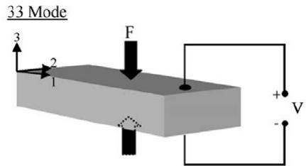
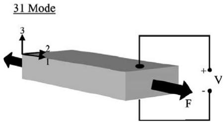
Flexible piezoelectric materials are attractive for power harvesting applications because of their ability to withstand large amounts of strain. Larger strains provide more mechanical energy available for conversion into electrical energy. A second method of increasing the amount of energy harvested from a piezoelectric is to utilize a more efficient coupling mode. Two practical coupling modes exist; the −31 mode and the −33 mode. In the −31 mode, a force is applied in the direction perpendicular to the poling direction, an example of which is a bending beam that is poled on its top and bottom surfaces. In the −33 mode, a force is applied in the same direction as the poling direction, such as the compression of a piezoelectric block that is poled on its top and bottom surfaces. An illustration of each mode is presented in figure 3. Conventionally, the −31 mode has been the most commonly used coupling mode: however, the −31 mode yields a lower coupling coefficient, than the −33 mode. Baker al (2005) have shown that, for three different types of piezoelectric materials, the −31 mode has a lower coupling coefficient, than the −33 mode. Upon comparing a piezoelectric stack operating in the −33 mode to a cantilever beam operating in the 31 mode of equal volumes, however, it was observed that, although the stack was more robust and had a higher coupling coefficient, the cantilever produced two orders of magnitude more power when subjected to the same force. This result is due to the high mechanical stiffness in the stack configuration which makes straining of the material difficult. It was concluded that in a small force, low vibration level environment, the −31 configuration cantilever proved most efficient, but in a high force environment, such as a heavy manufacturing facility or in large operating machinery, a stack configuration would be more durable and generate useful energy. This result was also presented by Roundy et al (2003) who concluded that the resonant frequency of a system operating in the −31 mode is much lower, making the system more likely to be driven at resonance in a natural environment, thus providing more power.
Table 1. Summary of several piezoelectric materials investigated.
| Author | Type of material | Advantages/disadvantages | Power harvesting capabilities |
| Lee et al (2005) | Monolithic PZT | Most common type of device. Not flexible.Susceptible to fatigue crack growth during cyclic loading | N/A |
| Lee et al (2004, 2005) | PVDF film coated with PEDOT/PSS electrodes | Resistance to fatigue crack damage to electrodes | N/A |
| Mohammadi et al (2003) | Piezofiber composite | Increased flexibility | 120 mW from 34 × 11 mm plate of 5.85 mm thickness |
| Churchill et al (2003) | Piezofiber composite | Increased flexibility | 7.5 mW from 130 × 13 mm patch of 0.38 mm thickness |
| Sodano et al (2004a) | MFC composite, quick pack IDE, quick pack | MFC-flexibilityMFC and quick pack IDE—low-capacitance devices quick pack—energy harvesting capability | quick pack proved to harvest the most energy |
| Sodano et al (2005a) | Monolithic PZT, quick pack, MFC | MFC-flexibility quick pack and monolithic PZT—energy harvesting capability | PZT proved to be most efficient (6.8% for random vibration excitation) |
text_image
33 Mode F 3 2 1 + V
text_image
31 Mode 3 2 1 + V
F
Figure 3. Illustration of −33 mode and −31 mode operation for piezoelectric materials. (Figure from Roundy et al 2003, © 2003, with permission from Elsevier.)
Analytically, Yang et al (2005) have shown that, for a piezoelectric plate operating in the −33 mode, the output power of the device is proportional to the coupling coefficient, k, and the dielectric constant, ε. This confirms that devices with higher coupling coefficients will produce more power and behave more efficiently. Also, through their analytical calculations it was shown that, when the driving frequency is near a resonant frequency of the system, the output power is significantly increased. This is because when a system operates at resonance, much higher displacements and strains are observed than when operating slightly above or below resonance. Richards et al (2004) present a similar study in which a general approach to establishing the relationship between the coupling coefficient, quality factor, Q, and the efficiency is presented. The quality factor, Q, is inversely proportional to the damping in an oscillating system caused by energy loss via heat transfer. A system with a high Q value, therefore, does not lose much energy to heat, thus more energy is available for harvesting through a piezoelectric device. Richards et al found that generally, high efficiencies can be achieved with moderate coupling coefficients but large quality factors are necessary for the reasons described above. It should be noted, however, that higher coupling coefficients do lead to greater efficiencies. It can be concluded that the quality factor of systems deployed in field applications is an important design issue in order to optimize the power harvesting ability of the system.
Cho et al (2005a) continued the work presented by Richards et al (2004) by analytically optimizing the coupling coefficient in a piezoelectric power harvesting system and then testing the optimization scheme experimentally. First, an analytical model was created for a rectangular thin-film PZT membrane consisting of two layers, a passive elastic material and a piezoelectric material with a variable sized electrode on either side. Their model predicted that the coupling coefficient increases with electrode size and reaches a maximum when the electrode covers 42% of the membrane area. It was also found that the coupling coefficient can be increased by increasing the stiffness of the passive elastic layer and that an optimal piezoelectric layer thickness exists for each substrate layer thickness. Lastly, of all the process and design parameters, the residual stress was found to have the greatest effect on the coupling coefficient. Decreasing the residual stress in the device leads to significant gains in the coupling coefficient. Experimentally, Cho et al (2005b) show that an electrode coverage of about 60% proved to give the best coupling. Also, for a substrate thickness of 2 μm, increasing the PZT thickness from 1 to 3 μm increases the coupling coefficient by a factor of about four. Finally, for a membrane with an initial residual stress of 80 MPa, the coupling coefficient increased by 150% through reductions in the stress.
text_image
Piezoelectric Layer Metal Layer (a) (b) (c)
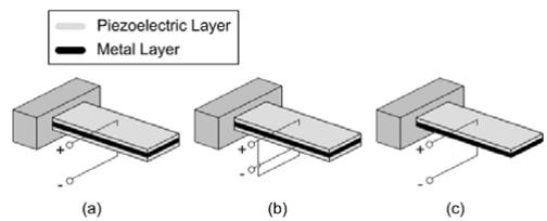
Figure 4. (a) A series triple layer type piezoelectric sensor. (b) A parallel triple layer type piezoelectric sensor. (c) A unimorph piezoelectric sensor.
Another method of changing the configuration of a system in order to improve its power harvesting capabilities is to add multiple pieces of piezoelectric material to the system. Many conventional systems consist of a single piezoceramic in bending mode, referred to as a unimorph. The design of such a unimorph cantilever beam is described by Johnson et al (2006). Another common configuration is a bimorph, which consists of two bonded piezoelectrics in bending. Sodano et al (2004c) developed a mathematical model to predict the energy generated from a piezoelectric bimorph cantilever beam. Upon experimentally validating the model, a maximum error of 4.61% was found.
Ng and Liao (2004, 2005) presented two types of bimorphs along with a unimorph piezoelectric harvester. The unimorph consisted of a single piezoelectric patch mounted to a metallic cantilever beam. The first bimorph, referred to as the series triple layer, consisted of two piezoelectrics with a metallic layer sandwiched between them. The piezoelectric patches were connected electrically in series. The second bimorph, called the parallel triple layer, was the same as the series triple layer except that the piezoelectrics were connected electrically in parallel. The configuration of each device can be seen in figure 4. Findings showed that under low load resistances and excitation frequencies the unimorph generated the highest power, under medium load resistances and frequencies the parallel triple layer had the highest power output, and under high load resistances and frequencies the series triple layer produced the greatest power. This result is due to the concept that maximum power transfer from the piezoelectric device occurs when the load resistance is matched to the impedance of the piezoelectric device. A series connection increases the device impedance, leading to more efficient operation at higher loads, as was found.
In a similar study, Mateu and Moll (2005) analyzed a homogeneous bimorph which contained two pieces of piezoelectric material bonded to each other, a heterogeneous bimorph that contained two pieces of piezoelectric material bonded on either side of a non-piezoelectric material that simply provided elastic function, and a heterogeneous unimorph that consisted of a single piezoelectric patch bonded to a non-piezoelectric beam. It was determined that, for harvesters with the same piezoelectric material volume, the heterogeneous unimorph generated the most power because the piezoelectric material was furthest away from the neutral bending axis, thus causing higher strains in the active material and greater energy generation.
Jiang et al (2005) also investigated methods of increasing the efficiency of a piezoelectric bimorph. Their study involved modeling a cantilever bimorph with a proof mass attached to its end and using the model to determine the relationship between performance and physical and geometrical parameters. Results showed that, by both reducing the thickness of the bimorph’s elastic layer and by increasing the proof mass attached to the end of the cantilever, the resonant frequency of the system was substantially decreased. The maximum power harvested was shown to be greater for lower resonant frequencies. Anderson and Sexton (2006) arrived at a similar conclusion when optimizing the physical and geometrical parameters of a similar bimorph. By varying the proof mass, length, and width, they discovered that changes to the proof mass had the largest effect on the power harvested by the system.
The work of Gurav et al (2004) focused on optimizing the power output of micro-scale piezoelectric cantilever harvesters. Taking into consideration the high tolerances on shapes and the large variation in material properties involved with micro-scale machining operations, an uncertainty-based design optimization technique was utilized to determine the best possible design parameters for a micro-scale cantilever power harvester. In order to avoid impossible designs, limits were set on each of the geometrical parameters to be optimized. The resulting geometry obtained from the optimization routine was analytically compared to the geometry of a baseline cantilever and a 30% increase in power output over the baseline design was found for the optimized geometry.
Another effective way to improve the energy output of a power harvesting device is to stack a large number of thin piezoceramic wafers together, called the stack configuration, with the electric field applied along the length of the stack. Platt et al (2005a) investigated power harvesting using approximately 145 PZT wafers stacked mechanically in series, but electrically in parallel, to form a 1.0 cm square stack with a height of 1.8 cm. A solid monolithic cylinder of PZT with a diameter of 1.0 cm and a height of 2.0 cm was tested for comparison. The monolithic cylinder had a low capacitance of about 47 pF and a very high open circuit voltage of around 10 000 V. The PZT stack, however, had an increased capacitance in the range of 1–10 μF and a decreased open circuit voltage of around 30 V. Through experimentation it was found that stacked and monolithic PZTs of the same geometry produce the same power if the load resistance is matched to the physical system, but that the matching load is in the k- range for stacked configurations and in the G- range for monolithic elements. It was concluded that both the voltage output and the matching resistive load are much more manageable in a PZT stack than in a monolithic configuration, thus making the stack a more useful option. Table 2 presents a summary of the various devices discussed that use multiple piezoelectric patches.
Table 2. Summary of various devices using multiple piezoelectric patches.
| Author | Piezoelectric configuration | Advantages/disadvantage |
| Ng and Liao (2004, 2005) | Unimorph, Series triple layer bimorph,Parallel triple layer bimorph | Unimorph—good under low excitations and loadsSeries triple layer—good under high excitations and loadsParallel triple layer—good under medium excitations and loads |
| Mateu and Moll (2005) | Homogeneous bimorph,heterogeneous bimorph,heterogeneous unimorph | Heterogeneous unimorph generated most power |
| Platt et al (2005a) | 145 stacked PZT wafers,solid monolithic PZT cylinder | Matching resistance is in kΩ range for stacked and in the GΩ range for monolithic |
Similar to some of the stacked configurations using multiple pieces of piezoelectric material described above, Bayrashev et al (2004) have developed a method of piezoelectric power harvesting in which a piezoelectric patch is sandwiched between two magnetostrictive materials. When subjected to a magnetic field, the magnetostrictive material changes shape and causes the piezoelectric patch to strain and harvest energy. An experimental device containing a 0.5 mm thick, 7 mm diameter piezoelectric patch surrounded by two 1.5 mm thick, 7 mm diameter Terfenol-D discs was created and tested. The device was subjected to a low frequency magnetic field and was found to generate high voltages up to 285 V, and power in the range of 10–80 μW, depending on how far away the device was located from the magnetic field source. The overall efficiency of the device was found to be 3.1%.
The most commonly used geometrical configuration in piezoelectric power harvesting is the rectangular cantilever beam. The cantilever beam harvester has been well developed and has proven to be easy to implement and effective for harvesting energy from ambient vibrations. Various other geometries, however, have been studied in order to improve upon the conventional cantilever design and to better suit other power harvesting applications. Mateu and Moll (2005) presented a brief analytical comparison between a rectangular cantilever and a triangular shaped cantilever with the large end clamped and the small end free. It was proven mathematically that a triangular cantilever with base and height dimensions equal to the base and length dimensions of a rectangular beam will have a higher strain and maximum deflection for a given load. Higher strains and deflections in piezoelectric materials translate to higher power outputs; therefore, a triangular cantilever beam will produce more power per unit area than a rectangular beam.
Additionally, Roundy et al (2005) suggested that, with an increasingly trapezoidal shaped cantilever, the strain can be more evenly distributed throughout the structure as opposed to a rectangular beam that contains a non-uniform strain distribution. Also stated was that, for the same volume of PZT, a trapezoidal cantilever can generate more than twice the energy than a rectangular beam. Continuing the work of Roundy et al (2005), Baker et al (2005) experimentally tested a nearly triangular trapezoidal cantilever against a rectangular cantilever of the same volume and determined that the trapezoidal beam produced 30% more power than the rectangular beam. It was concluded that, by using a trapezoidal configuration, a smaller and less expensive harvester could be used to satisfy a given power requirement.
Rather than altering the profile of the conventional rectangular cantilever, Mossi et al (2005) changed the end constraints on the beam and created a so-called ‘unimorph prestressed bender’. This is an initially curved, arc shaped, rectangular piezoelectric device that elongates when a force is applied to the top of the arc. The elongation causes strain in the active material which produces a voltage. The device is simply supported and allows for movement only in the lateral direction. Typically, these devices are used as actuators; however, research (Kymissis et al 1998, Yoon et al 2005) has shown that they are capable of producing useable energy as power harvesters. The effects of varying different physical parameters of the prestressed bender mentioned in this study are presented. The conductivity of the adhesive layer between the piezoelectric material and the passive metal layer, the thickness of the PZT layer, the thickness and type of the metal layer, and the width of the device were investigated. Varying the metal thickness and type had a significant effect on the amount of curvature of the beam, also known as dome height. Larger dome heights correspond to larger strains and energy generation when the harvester is compressed, thus altering the metal thickness and type can affect the power output of the bimorph. The most notable increase in power generation occurred, however, when the conductivity of the adhesive layer was increased by adding nickel particles. This resulted in a 15.2% increase in the energy produced.
Danak et al (2003) also researched ways to optimize the design of an initially curved PZT unimorph power harvester. A mathematical model was created that predicts the power output of the device. From this model, relationships between generated charge and initial dome height, substrate thickness, PZT thickness, and substrate stiffness were established. It was found that increasing the dome height gave the greatest increase in charge output. Increasing the substrate and PZT thickness both gave higher charge outputs; however, increasing the substrate thickness had a greater effect than increasing the PZT thickness. Lastly, it was found that, by increasing the stiffness of the substrate, more charge could be generated.
In a subsequent study, Yoon et al (2005) not only investigated the effects of altering the initial dome height, substrate thickness, and substrate stiffness, but also studied the effects of beam width and length, and experimentally tested various configurations of unimorph benders to validate the mathematical findings. Analytically, it was confirmed that increasing the initial dome height, substrate thickness, and substrate stiffness all yield higher charge output. Additionally, research showed that increasing both the width and length of the unimorph helped increase charge output, but that increasing the width is more effective than increasing the length. Experimentally, nine PZT unimorph samples were fabricated in which length and substrate thicknesses were varied. Although it was not possible to vary all of the parameters that were analytically examined, the experimental results showed good correlation with the predicted results, thus validating the model used in this study. The conclusion can be made that prestressed unimorph PZT power harvesters will be more efficient when the dome height, substrate thickness, substrate stiffness, length, and width are increased.
Similar to the studies conducted on initially curved unimorphs, Baker et al (2005) developed a novel configuration in which a piezoelectric beam is compressed and fixed at both ends with pin connections. The beam is loaded up to the critical buckling load. The so-called ‘bi-stable’ device generates power by snapping from one stable mode to another. Experimentally, the same beam was tested in both the bi-stable, compressed configuration and in a non-compressed pin–pin supported configuration. Experimental results show that the bistable beam has a wider range of performance as the excitation frequency is changed, and that it consistently has 30%–100% more available power than the uncompressed beam.
The above research has focused on energy generation using rectangular or trapezoidal configurations. Research has also been conducted on harvesting from circular shaped piezoelectrics. Ericka et al (2005) have investigated ways to maximize the power output from ambient vibrations through the use of a unimorph membrane transducer. The unimorph consists of a circular brass layer with a slightly smaller circular PZT layer of 25 mm diameter bonded to its surface. The brass disc is attached to the inside face of a thick aluminum ring for support. When subjected to a 2g acceleration force at various frequencies, the membrane transducer was found to produce a voltage of 24 V at its resonance frequency of 2.58 kHz, through a load resistance of 1 M-. A maximum power output of 1.8 mW was obtained under the same 2g acceleration but with a matched load of 56 k-. Also, by increasing the magnitude of the acceleration on the device, more power was harvested. The experimental results of this study show that the power harvested from a unimorph membrane transducer can be increased by operating at the resonant frequency of the device, by subjecting the device to high accelerations, and especially by matching the electrical load resistance.
Kim et al (2005a) investigated the use of clamped circular plates to be used in harvesting power from pressure sources. This initial study focused on analytically modeling a clamped circular plate consisting of a piezoelectric layer bonded to a substrate layer of identical diameter. Analysis was done on the effects of varying the thickness ratio of piezoelectric material to substrate material, and also on the effects of varying the electrode pattern of the piezoelectric. In a subsequent study by Kim et al (2005b), the analytical results of altering the electrode pattern were tested experimentally, and it was found that a plate with part of the electrode surface repoled to provide reverse polarity from the unmodified section produced the greatest power output. A plate repoled beyond a radius of 0.707a, with a being the total radius of the plate, proved to be the most efficient, producing 28 mJ of energy.
text_image
Metal End-Cap φd dc tp PZT φc φ
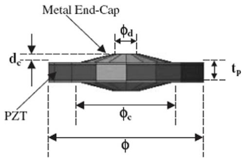
Figure 5. Piezoelectric ‘cymbal’ transducer. (Figure from Kim et al 2004, reproduced with permission.)
Kim et al (2004) developed a novel circular configuration for power harvesting called a piezoelectric ‘cymbal’ in which two dome-shaped metal end-caps are bonded on either side of a piezoelectric circular plate, as shown in figure 5. By using cymbal end-caps, the stress applied to the piezoelectric material when compressed is more evenly distributed than in a conventional stack configuration. By distributing the stress throughout the piezoceramic material, the efficiency of the power harvester is increased as a larger amount of the material is actively generating energy. End-caps also allow greater forces and higher frequency loads to be applied to the structure, both of which help increase the power output. Under a force of 7.8 N at a frequency of 100 Hz, a 29 mm diameter, 1 mm thick piezoelectric plate with steel end-caps 0.3 mm thick, 17 mm in diameter, and 1 mm tall produced 39 mW of power into a load of 400 k-. In a follow-up study, Kim et al (2005) subjected a cymbal transducer of 29 mm diameter, 1.8 mm thickness with 0.4 mm thick steel end-caps to a 70 N force at 100 Hz. The harvester generated 52 mW of power into a load of 400 k-. Results show that cymbal transducers are capable of withstanding high force applications while producing useable power. A summary of the various piezoelectric geometries reviewed is presented in table 3.
One final method of improving the efficiency of piezoelectric power harvesters involves tuning the device so that its resonant frequency matches the frequency of ambient vibrations. Cornwell et al (2005) investigated the concept of attaching a tuned auxiliary structure, similar to a vibration absorber, to a host structure to maximize the mechanical energy available to the harvester in order to enhance power harvesting efficiency. Analytically, it was shown that the auxiliary structure should be tuned to the frequency of the most dominant vibration mode of the host structure and placed at the location of maximum displacement for that mode. Also, it was found that the length of the auxiliary structure should be maximized and that a lower elastic modulus helps to increase the deflection in the beam, thus improving power output. Experimentally, a conventional piezoelectric harvester was attached to a host structure and produced 0.057 V. A mistuned auxiliary structure was then used and a voltage output of
Table 3. Summary of various piezoelectric geometries investigated.
| Author | Piezoelectric configuration | Advantages/disadvantages |
| Mateu and Moll (2005) | Rectangular cantilever and triangular cantilever | Triangular configuration capable of higher strains and higher power generation |
| Roundy et al (2005) | Trapezoidal cantilever | Trapezoidal configuration allows strain to be evenly distributed increasing efficiency |
| Baker et al (2005) | Rectangular cantilever and trapezoidal cantilever | Trapezoidal beam produced30% more energy than rectangular |
| Mossi et al (2005) | Unimorph prestressed bender | Initially curved shape can help improve harvesting capability |
| Danak et al (2003) | Initially curved PZT unimorph | Initially curved shape can help improve harvesting capability |
| Yoon et al (2005) | Initially curved PZT unimorph | Initially curved shape can help improve harvesting capability |
| Baker et al (2005) | ‘Bi-stable’ pin-pin connected initially compressed beam | ‘Bi-stable’ device has wider range of performance versus excitation frequency than an uncompressed beam |
| Ericka et al (2005) | Unimorph circular membrane | Capable of harvesting energy from high accelerations |
| Kim et al (2005a, 2005b) | Clamped circular plates | Capable of harvesting energy from fluctuating pressure sources |
| Kim et al (2004) | Piezoelectric ‘cymbal’ | Improved efficiency through load distribution. Capable of withstanding high loads |
0.133 V was measured. Lastly, a tuned auxiliary structure was used and 0.335 V was measured. The voltage increase by five times corresponds to an output power increase of 25 times. It was concluded that an auxiliary structure, even when mistuned, can significantly increase power harvesting capabilities.
Roundy and Zhang (2005) further developed the idea of tuning the resonant frequency of a piezoelectric device to match the frequency of ambient vibrations. The concept of active self-tuning was explored. Active self-tuning is defined as a process in which power must be continually applied to the system to achieve resonant frequency matching. Passive self-tuning, on the other hand, only requires power to be supplied initially in order to tune the structure and then power is turned off while maintaining the new resonant frequency. Through mathematical modeling, it was shown that an active actuator that tunes the natural frequency of the system by either altering the stiffness or mass of the system will never result in a net increase in electrical power output. This discovery assumes that the system is well represented by the secondorder model developed by Williams and Yates (1995). In order to validate this conclusion, a PZT generator with an active tuning electrode was created in which the stiffness of the device could be altered by varying the voltage applied to the tuning electrode. When testing the device, it was found that, although the tuning circuit was able to alter the resonant frequency of the device, the power required to tune the frequency far outweighed the increase in power output. These results validated the conclusion that an active self-tuning device will never result in an increase in energy generation. It was suggested that passive self-tuning actuators be investigated for improving the efficiency of piezoelectric power harvesting.
In a similar study, Wu et al (2006) created an actively tuned power harvesting system in which the resonant frequency of a bimorph actuator was altered through the use of a microcontroller. The proposed technique implements tuning circuitry attached to the upper piezoelectric element in the bimorph, and harvests energy from the lower piezoelectric element. A microcontroller capable of altering the value of its capacitive load is attached to the top piezoelectric element. By varying the capacitive load, the effective stiffness of the beam can be altered. Analytically it was estimated that a cantilever bimorph excited by a shaker could see an increase in power output of up to 30%. The technique was experimentally validated by attaching a cantilever bimorph actuator to a vibration shaker and attaching a microcontroller to the cantilever. When subjected to a random frequency excitation, the average power output of the device increased by 27.4% when the tuning circuitry was used. This result does not take into consideration the additional power requirements associated with the operation of the microcontroller. It was noted, however, that some existing microcontrollers use only microwatts of power, and that these controllers would be best suited for this application.
In order to create a completely passive system, Shahruz (2006a, 2006b) designed a power harvesting device capable of resonating at various frequencies without the need for adjustment. The device consisted of multiple cantilever beams with various lengths and end masses attached to a common base. Each cantilever had a unique resonant frequency, the combination of which into a single device created a so-called ‘mechanical bandpass filter.’ By properly selecting the length and end mass of each beam, some of which had no end mass, the overall device was designed to have a wide band of resonant frequencies. An analytical model was developed to assess both the performance and limitations of the device. It was found that a limited frequency band exists in which the device optimally converts ambient vibrations into electrical energy. Although the power harvesting device was analyzed analytically, a physical device was not created and an experimental validation was not performed, therefore, the true performance of the device was not measured. When compared to alternative tuning methods, the ‘mechanical bandpass filter’ operates efficiently over a large frequency range, however, the device requires an array of piezoelectric cantilever beams, resulting in a significant increase in both size and cost. Additionally, a more complex electric circuit may be necessary to extract energy from each piezoelectric beam.
text_image
Piezoelectric elements Vibrating beams Mechanical energy transfer teeth m Secondary Vibrating units k Y(t) Vibrating platform
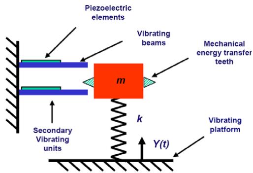
Figure 6. Schematic of a typical energy harvesting power source using the two-stage design. (Figure from Rastegar et al 2006, reproduced with permission.)
Rastegar et al (2006) investigated another method of designing a passive system. A two-stage energy harvesting design was suggested in which energy from systems that vibrate with very low frequencies, in the 0.2–0.5 Hz range, can be converted into potential energy in the first stage, and then transferred to a system with a much higher natural frequency in the second stage. One example of such a two-stage system is shown in figure 6, where the low frequency vibration energy of the mass is transferred to high frequency vibrations in the piezoelectric elements as the mass passes over and excites the piezoelectric cantilevers. Advantages of this method include the possible implementation of power harvesting devices on systems with very low frequency vibrations, and eliminating the need to tune the resonant frequency of the piezoelectric device to match that of its host. The research, however, only presents the design method and does not perform any experimental tests to validate the method. The main challenge in designing an effective two-stage system is the method of transferring energy from the first stage to the second stage while minimizing energy losses from friction and impact. It is proposed that systems without physical contact, such as those using magnets to transfer energy, be investigated. Table 4 presents a summary of the various tuning schemes used to improve the efficiency of piezoelectric power harvesting.
3. Improving efficiency and power generation through circuitry and method of power storage
In addition to improving power harvesting efficiency and energy generation capabilities through altering the configuration of the device, recent research has also focused on modifying the power harvesting circuitry and storage medium as a means for improvement. The following research studies have investigated various ways to alter the electrical circuit that extracts and stores energy from a piezoelectric device. The power storage capabilities of different storage media are also discussed.
Ng and Liao (2004, 2005) developed a power harvesting circuit to extract energy from a cantilever beam piezoelectric harvester. It was found that the instantaneous power harvested by the piezoelectric device was too small to be used in practical applications so a power harvesting circuit was developed that releases the energy in so-called ‘burst mode.’ The energy generated by the piezoelectric material is first rectified with a diode and then stored in a reservoir capacitor. A voltage monitoring circuit is connected to the reservoir capacitor and releases energy from the capacitor in burst mode. The circuit senses the voltage across the reservoir capacitor and allows the capacitor to discharge through the load once a certain high voltage level, called the release voltage, is detected. Additionally, the circuit stops allowing the capacitor to discharge once the voltage reaches a certain low level, called the detect voltage. The power harvesting circuit operating in burst mode was found to have an efficiency of 46%. In a similar study, Tayahi et al (2005) investigated piezoelectric power harvesting circuitry to be used in low frequency applications such as walking. A circuit was developed that contained a rectifier, bucket capacitor, and a Linear Technologies LTC1474 voltage regulator that supplied voltage to the load. Conceptually, the high efficiency of the converter should help improve the efficiency of the harvesting circuit: however, the circuit was only discussed and not tested.
Han et al (2004) studied ways to extract power efficiently from a micro-scale piezoelectric generator. The power harvesting circuit developed consisted of two stages: a rectifier, followed by a DC–DC converter. A charge pump type DC– DC converter was chosen because it consists of capacitors and MOSFETs (metal oxide semiconductor field-effect transistor), which can easily be incorporated onto a single chip, and because of the capacitive nature of piezoelectric devices which allows them to output a high voltage with low current. A synchronous rectifier was used in the first stage to improve efficiency. When analytically and experimentally compared to the traditional diode–resistor pair rectifier, the synchronous rectifier extracted over 400% more power. The increase in power takes into consideration the energy requirements of the comparators that must be used in the synchronous rectification scheme. The efficiencies of the rectifiers were also experimentally obtained. The standard diode–resistor pair rectifier had an efficiency of 34%. By utilizing a synchronous rectifier, the efficiency was increased to 92% when the circuit was actively harvesting vibration energy. The potential back flow of energy from the storage medium to the system components when the system is idle was not discussed, but could have an effect on the overall efficiency of the synchronous method.
Shenck and Paradiso (2001) investigated ways to improve the efficiency of a power storage circuit for use with shoemounted piezoelectric generators. The circuit was designed to provide sufficient power to operate a radio frequency tag mounted in a shoe, capable of transmitting a short-range identification code during walking. Initially, a circuit utilizing a linear regulation scheme was designed and tested. Although the initial circuit was found to be simple and require low power while idle, it was inherently inefficient. In an effort to increase the efficiency of their power harvesting circuit, an offline, forward-switching DC–DC converter was developed, consisting of inexpensive, readily available components. It was noted that for a shoe harvester that is mostly capacitive with a low excitation frequency, a resonant shunting circuit would be most ideal. Resonant shunting of this low frequency source, however, would require an inductance on the order of 105 H, which is not practical. Instead, a switching converter was developed. A detailed description of the converter design and operation is presented in the literature. When experimentally tested and compared to the original linear regulator circuit, the switching converter proved to harvest power more efficiently from the piezoelectric device. The switching circuit operated at an efficiency of 17.6%, more than twice the efficiency of the linear regulator. Additionally, the switching circuit provided power continuously during walking.
Table 4. Summary of various tuning schemes investigated.
| Author | Piezoelectric configuration | Advantages/disadvantage |
| Cornwell et al (2005) | Tuned auxiliary structure (passive device) | Auxiliary structure can greatly increase the power generated from a vibrating host. Structure must be precisely tuned for maximum power generation |
| Roundy and Zhang (2005) | Active self-tuning structure | Power required to actively tune the device is more than power harvested by device |
| Wu et al (2006) | Active self-tuning bimorph actuator | Average power increased by 30% when half of the piezoelectric device was altered through tuning circuitry. This result does not take into consideration the power consumption of the tuning circuitry |
| Shahruz (2006a, 2006b) | Mechanical bandpass filter system with multiple piezoelectric cantilevers tuned to different frequencies | Effective over a large frequency range Requires multiple piezoelectric patches, most of which remain inactive at a given frequency |
| Rastegar et al (2006) | Two-stage vibrating mass system | Capable of converting low frequency vibration to high frequency resonant vibration of piezoelectric cantilevers |
The research of both Ottman et al (2002) and Lesieutre et al (2004) involves improving the efficiency of power harvesting through implementation of a switching DC–DC step-down converter in the power harvesting circuit. The research investigates the effects of optimizing the duty cycle of the converter for a given excitation frequency. It was shown that the optimal duty cycle value changes drastically with excitation frequency. A step-down converter was chosen because the piezoelectric voltage is often very high and it must be reduced to a lower level that can be accepted by a battery or an electronic load. The converter presented operates in two stages. At high excitation frequencies, the converter is activated and a constant, near-optimal duty cycle is used. At low excitations, the optimal duty cycle varies considerably, and the power consumed by the converter circuitry overcomes the power harvested from the piezoelectric, so the converter is bypassed and the battery is charged directly from a rectifier circuit. Both analytical and experimental tests gave an optimal duty cycle of 2.8% for their system. When testing the performance of the step-down converter, it was found that, when using the optimal duty cycle of 2.8%, the converter outperformed the direct charging method at any excitation that produces above 25 V on the piezoelectric. The efficiency of the step-down converter was calculated to be between 0% and 70%, depending on excitation frequency. A maximum efficiency of 70% was found for excitations producing 48 V, and the converter harvested energy at over three times the rate of direct charging when operating at this point.
The work of Ottman et al (2002) and Lesieutre et al (2004) was further developed by Ammar et al (2005) who created an adaptive algorithm for controlling the duty cycle of a DC–DC buck converter. Again it was noted that the optimal duty cycle of the buck converter is related to the excitation frequency of the system. In order to improve the efficiency of their energy harvesting circuit, an adaptive algorithm that actively changes the duty cycle of the converter during operation was implemented. The proposed algorithm starts with an initial low duty cycle value and measures the current flowing into the battery. The controller then increments the duty cycle value and each time the duty cycle is incremented, the current flowing into the battery is measured and compared to the previously obtained current measurement. If the change in duty cycle results in an increase in current, the duty cycle is again increased. The process continues until the increased duty cycle no longer gives an increased current flow. A prototype circuit was developed and tested. When comparing the battery charge versus time for the adaptive circuit to a constant duty cycle converter, it was found that the adaptive circuit leads to a faster charge accumulation on the battery. However, the effects of the power draw from the adaptive circuitry were not investigated.
A self-adaptive power harvesting circuit has been developed by Lefeuvre et al (2005b) in which extraction of electric charge from a piezoelectric device is synchronized with the system vibration in order to improve the efficiency of the energy transfer process. The technique is termed ‘synchronous electric charge extraction’. The circuit used for this synchronous extraction contains a rectifying diode bridge and a flyback switching mode DC–DC converter. A control circuit is able to sense the voltage across the diode rectifier and, when that voltage reaches a maximum, the flyback converter is activated and charge is transferred to the battery. When the electric charge on the piezoelectric has been completely extracted, the control circuit deactivates the converter and stops energy transfer. The process continues when the next voltage maximum is detected, thus synchronizing the charge extraction with the mechanical vibrations of the system. When tested experimentally against a linear impedance-based converter design, the synchronous converter increased power transfer by over 400%. The flyback converter was found to have an efficiency of 70%.
text_image
Piezo I V Switching Device Cr R Vcc
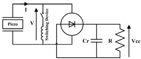
Figure 7. SSHI energy harvesting circuit.
In similar studies, Lefeuvre et al (2004), Badel et al (2005), and Guyomar et al (2005) investigate another method of synchronizing the electric charge extraction from a piezoelectric element with the vibrations of the system. The new technique is called ‘synchronous switch harvesting on inductor’ (SSHI), and is based on nonlinear processing of the piezoelectric voltage. The SSHI circuit contains an electronic switching device that is triggered on the maximum and minimum displacements of the piezoelectric device. The switching device and an inductor in series are placed in parallel with the piezoelectric before the rectifying diode bridge. After the diode bridge, a capacitor is placed in parallel with the battery. A circuit diagram of the SSHI system is shown in figure 7. Similar to the synchronous electric charge extraction technique described by Lefeuvre et al (2005b), the switching device closes on a displacement maximum, allowing charge to be transferred to the battery. Once the voltage on the piezoelectric element has been reversed, signaling that all of the charge has been removed, the switch is opened and energy transfer is stopped. The SSHI technique was both analytically and experimentally compared to a standard circuit containing only the diode bridge rectifier and capacitor. Results show that the SSHI circuit is capable of delivering a 400% increase in efficiency over the standard circuit.
In subsequent studies, Lefeuvre et al (2005a, 2006) considered an adaptation of the SSHI technique developed by Lefeuvre et al (2004) and Badel et al (2005). The electrical configuration of the switching device connection to the piezoelectric material was altered to investigate the effects of the change on the efficiency of the circuit. In these studies, the switching device was first placed in series with the piezoelectric material. The new technique is called series-SSHI. The configuration which places the switching device in parallel with the piezoelectric is renamed parallel-SSHI. Both SSHI techniques are compared to each other, to a standard circuit containing a diode bridge and a filter capacitor, and to the synchronous electric charge extraction technique described previously. In an experimental study, the performances of all four techniques were compared under two conditions. First, a constant force amplitude excitation was applied to the piezoelectric. Second, a constant displacement amplitude excitation was applied. Under each test, both the load resistance and the coupling coefficient, k2, were varied. Under a constant force excitation, all of the techniques gave the same maximum power output. The power obtained from the synchronous electric charge extraction technique, however, was not affected by the load resistance. Additionally, that technique gave the maximum power output with the lowest coupling coefficient, meaning a more efficient system. Under a constant displacement amplitude excitation, both SSHI techniques generated up to 15 times more power than the other techniques when the resistive load was matched to the system. Although both SSHI techniques harvested about the same maximum power, the matching resistive load of the series-SSHI technique was about four orders of magnitude lower than that of the parallel-SSHI technique. It was concluded that, under a constant force excitation environment, the synchronous electric charge extraction method will be the most efficient, and under a constant displacement excitation environment, the parallel and series-SSHI methods have the highest efficiency when resistive loads are matched.
In addition to developing more efficient means of removing charge from the piezoelectric device, researchers have also studied the device that the energy is accumulated or stored in. Ayers et al (2003) developed a piezoelectric power harvesting device and used the device to charge both a capacitor and a battery. The piezoelectric device was subjected to a 1 kN load following a sawtooth pattern at 0.66 Hz. When charging the capacitor, a linear relationship between voltage increase on the capacitor and the number of cycles was found. Charging a Panasonic ML616 rechargeable battery revealed a decreasing exponential voltage trend with the number of cycles. No direct comparisons between storage methods were presented.
Sodano et al (2005b) compared the storage capabilities of a capacitor and a nickel metal hydride battery. A PZT patch subjected to random vibration correlated to the vibrations found on an automotive air compressor was used to charge the capacitor and the battery. The random vibrations ranged from 0 to 1000 Hz. A relatively complex charging circuit was used to charge the capacitor, however, a simple full bridge rectifier and filter capacitor were used to charge the battery. The capacitor circuit used was similar to that developed by Kymissis et al (1998) and was demonstrated to function properly under the random vibration applied to the piezoelectric device. It was also shown, however, that the capacitor rapidly discharged, resulting in the output of the circuit to be high frequency pulses. When charging the battery, it was found that a voltage level of 1.2 V could be obtained in a 40 mA h battery in a few hours. The advantage of using the capacitor to store energy harvested by the piezoelectric is that the energy can be used almost instantaneously. Conversely, the battery takes a few hours to charge, however, the power stored in a battery does not have to be used immediately, but can be stored for later use. Additionally, a battery can deliver a constant power supply, unlike the capacitor. Lastly, the capacitor-based storage system described in this study, like many existing systems, must experience constant vibrations to supply power to a load, whereas a charged battery system can supply power even when no vibrations are present.
A later study conducted by Guan and Liao (2006) further investigated capacitors and rechargeable batteries as a means of storing energy generated by a piezoelectric device. The study involved comparing an electric double layer capacitor (EDLC) type supercapacitor, capable of storing hundreds of times more energy per unit volume or mass than a conventional capacitor, a nickel metal hydride rechargeable battery, and a lithium ion rechargeable battery. First, the charge–discharge efficiency was calculated for each storage medium. It was found that, at higher activation levels, each medium performed more efficiently compared to lower activation levels. Additionally, the supercapacitor observed the highest efficiency under all activation levels, with a maximum efficiency of 95%. The lithium ion battery was only slightly less efficient than the supercapacitor, yielding a maximum efficiency of 92%. The nickel metal hydride battery was least efficient with a maximum efficiency of 65%. The lifetime of each storage medium was also compared and it was concluded that both types of rechargeable batteries have limited lifecycles in the 300–1000 cycle range, where supercapacitors have virtually unlimited lifecycles. There are, however, disadvantages of using supercapacitors as opposed to rechargeable batteries. The self-discharge rate, for example, is higher in supercapacitors. After ten days the capacity drops from full charge to 85% of full charge. After 30 days, the voltage drops to 65% of full charge. Nickel metal hydride batteries drop to 70% in 30 days, and lithium ion batteries only drop to 95% in 30 days. Additionally, supercapacitors have much lower energy densities than rechargeable batteries. Nickel metal hydride batteries have energy densities on the order of , lithium ion batteries have densities around 120–140 Wh , while supercapacitors have densities of . It was concluded, however, that overall, supercapacitors are more attractive than rechargeable batteries because of their higher charge–discharge efficiencies and longer lifetimes, especially when the self-discharge rate is not significant because of constant charging, as in many power harvesting applications.
4. Implantable and wearable power supplies
As computer technology becomes increasingly integrated into various aspects of human life, the concept of harvesting the energy lost during everyday activities has become more appealing. The size and power requirements of both portable electronic devices including personal digital assistants and digital music players, as well as biomedical devices such as pacemakers have been rapidly decreasing. With this decrease has come an increase in the feasibility of harvesting electrical energy from the human body to power these devices. Batteries have typically been used to power portable electronics, however, battery technology has been one of the most lagging trends in mobile electronics. Starner and Paradiso (2004) showed that, from 1990 to 2003, battery energy density in mobile computing has only increased three-fold whereas other areas such as disk capacity, processor speed, and available memory have increased over 250 times. The slow evolution of battery technology has increased many researchers’ interests in developing power harvesting systems that utilize the energy lost in everyday human life.
When designing a human powered energy harvesting system, one must first consider the available energy sources involved with various human activities. Gonz´alez et al (2002) present an overview of the various sources of mechanical energy available in the human body. They classify human activities into two categories: continuous activities such as breathing and blood flow, and discontinuous activities like walking and upper limb movement. A large amount of research in biomechanical power harvesting has investigated discontinuous activities. According to Gonz´alez et al (2002), finger movement when typing on a keyboard can generate up to 19 mW of power, upper limb motion can generate 3 W of power during normal activity, and walking can generate 67 W of power at a pace of two steps per second. Continuous activities, on the other hand, generate considerably less power. Blood flow can generate 0.93 W: however, only a small portion of this can be harvested without adversely affecting the heart. Additionally, chest expansion during breathing can generate 0.83 W of power.
Niu et al (2004) also investigated the energy available through several human body motions. Their research included movements such as joint motion, whole-body center mass motion, walking, and heel strike. It was found that ankle, knee, hip, elbow, and shoulder motion can generate up to 69.8 W, 49.5 W, 39.2 W, 2.1 W, and 2.2 W, respectively. Wholebody center mass motion, which assumes that a mass is being carried and follows the same trajectory as that of the center of mass of a human, can generate 1 W of power. Lastly, it was reported that heel strike was capable of supplying 2 W of power at a pace of two steps per second. Upon evaluating the potential energy sources, the researchers determined that heel strike would be the best candidate mainly because of the ease of incorporating a piezoelectric power harvester into a shoe. Theoretical calculations were performed and results showed that a PVDF plate inserted into a shoe that acts in compression mode would generate at 544 V, and a PZT plate would generate 14 at 45 V. These low output power values caused a focus to be placed on heel strike utilizing the bending mode: however, difficulties in translating energy from the foot to the piezoelectric caused minimal improvements to be seen.
The research of Renaud et al (2005) focused on the possibility of harvesting power from wrist and arm motion during walking. Upon investigations, it was determined that a spring mass resonant system is not well suited for arm harvesting because of the low frequency of motion involved with arm movement. A non-resonant system, therefore, was proposed. This system contained a mass that slides freely inside a frame, and at either end of the frame there are piezoelectric cantilever beams that harvest energy as the frame vibrates from the impact of the mass. Although the system was not built, analytical modeling showed that a maximum of 40 of power would be produced when positioned on the wrist of a person walking.
In addition to analyzing the energy available from human activities, many researchers have modeled and experimentally tested human powered energy harvesting systems. Sohn et al (2005) both theoretically modeled, validated through the finite element method, and experimentally tested a film-based piezoelectric power harvester that uses fluctuating pressure sources such as blood flow to harvest energy. Several square and circular PVDF films were modeled using the finite element method, and it was found that a maximum power output of 0.61 was generated for a circular sample with a radius of 5.62 mm and a thickness of 9 μm when subjected to a 5333 (almost the same magnitude as human blood pressure) uniformly distributed pressure. In comparing the maximum power output obtained via finite element analysis to theoretical results, the error was less than 8%. Finally, an experimental apparatus was created that contained a circular PVDF film with a thickness of 28 μm placed in an aluminum jig that contained both an inlet and an outlet port allowing fluid to be pumped in and out of the jig. The film was subjected to a sinusoidal pressure of 5333 N at 1 Hz and generated 0.33 μW of power. Calculations were carried out that showed a chip requiring 10 mW of power to transmit data such as DNA information could be operated twice a day when powered by a circular plate.
text_image
Tibal Tray Piezoelectric Elements Stem Load Distribution Plate 75mm Bearing
Figure 8. Self-powered total knee replacement components. (Figure from Platt et al 2005a, reproduced with permission.)
text_image
Femoral Implant Prototype Implant Faxial Femur Tibia Faxial
Figure 9. Self-powered total knee replacement test set-up. (Figure from Platt et al 2005a, reproduced with permission.)
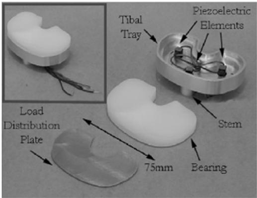
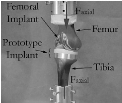
Platt et al (2005a) developed an in vivo piezoelectric harvester and sensor to be used in self-powered total knee replacement units. The piezoelectric units are capable of both sensing important phenomena in the knee such as abnormally high forces exerted on the joint, degradation, and misalignment, as well as providing the necessary power to run the sensing circuitry. An experimental model was created that incorporated both sensing and power harvesting capabilities into a total knee replacement unit. Tests were performed on the set-up shown in figures 8 and 9 using a standard 2600 N force profile to simulate the axial force in the knee during normal walking. A maximum of 4 mW of raw power and 0.85 mW of regulated power was generated. The power harvested by the unit proved to be enough to satisfy the power requirement of an internal microprocessor capable of transmitting valuable information about the condition of the unit. A subsequent study by Platt et al (2005b) showed that, by subjecting the total replacement knee unit to a 900 N standard force profile, about
text_image
Insole PZT dimorph Metal midplate PZT unimorph PZT unimorph PVDF stave Sole
Figure 10. A PZT dimorph and PVDF stave. (Figure from Shenck and Paradiso 2001, reproduced with permission.)
4.8 mW of continuous raw power was generated by combining three stacks, each of approximately 145 layers of piezoelectric material, into the unit. The output power was proven to be capable of powering many existing low-power microprocessors and sensors.
Perhaps the most common type of human powered energy generation involves implanting piezoelectric material into shoes. Shoe inserts are attractive not only because of their ability to convert everyday human activity into useful energy, but because of their ease of implementation. Mateu et al (2003) modeled and experimentally tested two piezoelectric films inserted into a shoe. The films were connected in parallel for increased charge generation. When subjected to a stress corresponding to that produced by a human weighing 68 kg during normal walking conditions and connected to a 500 kload, the analytical model and experimental data show good correlation. The results indicated that approximately 18 μW of power could be generated under these conditions.
In a later study, Mateu and Moll (2005) worked to obtain an optimized configuration of bending beams in shoes. Their research involved examining the combination of materials used to create the piezoelectric harvester as well as the coupling mode and shape of the harvester. A homogeneous bimorph, heterogeneous bimorph, and a heterogeneous unimorph were compared in the −31 and −33 coupling modes, with distributed and point loads, and with both rectangular and triangular shapes. Their study involved testing various PVDF films arranged in different configurations and it was found that a heterogeneous unimorph with a distributed load applied to a simply supported triangular beam provided the greatest power output.
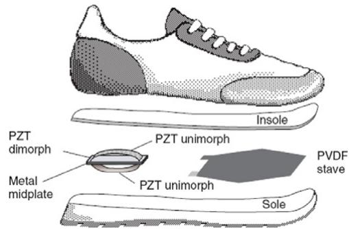
In addition to investigating PVDF film in bending mode, Shenck and Paradiso (2001) also researched harvesting the energy lost during heel strike using prestressed PZT unimorphs. Their research focused on implementing effective power harvesters into shoes while maintaining the design and comfort of the shoe. When testing the so-called PVDF ‘stave,’ it was implanted into the front of an athletic shoe because of the shoe’s toe flexibility. The average power delivered by the stave to a 250 k- load at a 0.9 Hz walking pace was 1.3 mW. The PZT unimorphs working off heel strike energy, on the other hand, were implemented into a US Navy work boot because of the boots’ rigid heel cup. The so-called PZT dimorph, consisting of two initially curved unimorphs in a clam shell configuration, produced 8.4 mW of power into a

text_image
APC (6) Standard Ultrasonic Air Transducer Compon Product Category Indicative Servi • Medical • Automatic • Protective • Turbine • Conventional • Airer • Engine UTA
Figure 11. Piezoelectric windmill converts air currents into electrical energy by vibrating piezoelectric benders. (Figure from Priya et al 2005, reproduced with permission.)
500 k- load. The PVDF stave and the PZT dimorph are illustrated in figure 10. In order to demonstrate the feasibility and usefulness of energy harvesting in shoes, a self-powered radio frequency (RF) tag was created and was shown to operate successfully when installed into the shoe. The tag was capable of transmitting a short-range 12-bit wireless identification (ID) code during walking.
5. Harvesting ambient fluid flows
Traditionally, piezoelectric power harvesting devices have been used to convert the ambient vibrations of a host structure into electrical energy. This requires the piezoelectric device to be securely attached to the vibrating host structure. Research has also been performed that investigates the possibility of converting energy from ambient fluid flows into useful electrical energy. The method still uses vibration of the piezoelectric material to generate electrical energy but converts fluid flow into vibration through vortices, oscillating flows, and rotational energy. The following studies discuss two ways in which fluid flows can act as an energy source for piezoelectric power harvesting devices.
One potential energy source is wind current. Windmills have been used to harvest energy for many years. The concept of using wind to apply strain to piezoelectric elements, however, is fairly new. Priya et al (2005) designed and tested a piezoelectric windmill energy harvesting device. The device contains a conventional fan that rotates when wind currents are present. The output shaft of the fan is connected to a cam system which is then connected to the input shaft of the piezoelectric windmill. The windmill consists of 12 piezoelectric bimorphs arranged in a circular array. One end of each bimorph is fixed while the other end is placed in contact with a rubber stopper connected to the input shaft of the windmill. When the fan rotates, the cam system causes the input shaft of the windmill to oscillate. The bimorphs are thus subjected to oscillatory motion. Additionally, the bimorphs used in the windmill were prestressed to have a bending of 1.77 mm at the end in contact with the stopper. Figure 11 presents a photograph of the test set-up showing the fan in the foreground and the piezoelectric windmill above the fan in the background. When experimentally testing the windmill, wind was applied to the fan such that the excitation frequency of the piezoelectric bimorphs was 6 Hz. At this excitation, it was found that a maximum voltage of 10.2 mW was obtained through a matching load resistance of 4.6 k-. In order to establish a model that could be used to represent the piezoelectric windmill, a subsequent study was performed. Priya (2005) used the same windmill configuration with the exception that only ten piezoelectric bimorphs were used. Additional experiments were run on the windmill and it was found that, as the wind speed increased, the power output of the harvester increased linearly. It was also found that, at wind speeds above 12 mph, the windmill could potentially be damaged. The maximum power output of the windmill was found to be 7.5 mW at a wind speed of 10 mph through a matching load resistance of 6.7 k-. Next, a mathematical model was created using piezoelectric beam theory. The model predicted that power output through a matched load increases linearly with increasing excitation frequency. This finding matches the linear increase in power output with wind speed found experimentally. A maximum power output of 6.9 mW was predicted at a wind speed of 10 mph. Although the model indicates some error when compared to experimental results, the study proves that harvesting power from ambient wind currents is feasible and can be modeled mathematically.
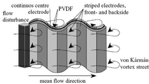
text_image
continuos centre flow disturbance electrode PVDF striped electrodes, front- and backside von Kármán vortex street mean flow direction
Figure 12. A PVDF flag generator. (Figure from Pobering and Schwesinger 2004, reproduced with permission.)
Flowing water is another source of energy provided by the ambient movement of a fluid. Hydroelectric power plants use the head pressure built up behind a dam to rotate a generator as the water flows through the dam. Recent research has investigated the use of piezoelectric materials submerged underwater in harvesting energy from flowing water. Taylor et al (2001) developed a so-called ‘energy harvesting eel’ made up of a long strip of piezoelectric polymer bimorph material. In order to produce adequate forces to cause the piezoelectric material to simulate the motions of a swimming eel, a bluff body is placed upstream of the power harvesting eel. The presence of the bluff body causes alternating vortices to be shed on either side of the obstruction. The resulting pressure differential in the water causes the piezoelectric bimorph to ‘wave,’ similar to the motions of an eel. A prototype eel that was 9.5 in long, 3 in wide, and 150 μm thick was created and tested in a flow tank. Results showed that the power output of the eel can be maximized when the so-called ‘flapping frequency’ matches the vortex shedding frequency. The voltage generated by the eel was measured and recorded for a water velocity of 0.5 m . A peak voltage of about 3 V was recorded.
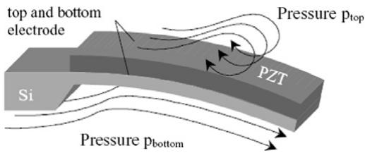
text_image
top and bottom electrode Si Pressure p_top PZT Pressure p_bottom
Figure 13. A cantilever bimorph generator. (Figure from Pobering and Schwesinger 2004, reproduced with permission.)
In a later study conducted by Pobering and Schwesinger (2004), the ability of a PVDF flag (see figure 12), similar to the eel created by Taylor et al (2001), and a cantilever bimorph (see figure 13) in harvesting energy from flowing water was tested. Theoretical calculations were first performed to determine the power harvesting capabilities of piezoelectric materials submerged in rivers. It was calculated that, in a river flowing at , piezoelectric materials could harvest 140 W m−2. When specifically analyzing both types of piezoelectric generators, it was determined that a bluff body would need to be inserted into the river, upstream of the devices, in order to create turbulent flow in the vicinity of the harvesters. Calculations were performed to obtain the power output of both devices. It was found that a PVDF flag could generate between 11 and of power. The power output of a cantilever with length, 3 mm width, and 60 μm thickness, on the other hand, was reported as . It was suggested that increases in power output could be obtained by decreasing the thickness and increasing the length of the cantilever. Next, the concept of combining multiple harvesters to create a larger scale generator was investigated. It was found that 100 000 small cantilever elements could be arranged in . Expanding even further, a 3D array of elements placed in a river could deliver approximately 68 of power. State-of-the-art wind turbines have a power density of about ; thus energy generation by piezoelectric elements submerged in a river is quite feasible and could show significant improvements above wind turbine technology. This concept, however, was not validated, and design issues regarding the ability to generate vortices acting over each device are expected.
6. Power harvesting in microelectromechanical systems
With the recent advances in computer and electronics technology, the possibility exists of creating miniaturized, selfpowered devices. The power requirements of some microscale chips are becoming so small that they can be powered by the energy scavenged from micro-scale piezoelectric power harvesters. Much of the recent power harvesting research in microelectromechanical systems (MEMS) has focused on the ability to supply power to wireless sensors. By incorporating power harvesting technology into wireless sensors, the cost of batteries and battery replacement can be eliminated. Additionally, the size of the sensor can be decreased by incorporating micro-scale power harvesters as an energy source.
In an effort to develop a micro-scale power harvester, Ammar et al (2005) designed a 1 μm thick piezoelectric cantilever beam with a seismic mass attached to its end. This micro-power harvester was to be used as the energy source for a compact wireless sensor node. In addition to designing the cantilever, an adaptive energy harvesting circuit was also developed to help optimize the mechanical to electrical energy conversion process. Although a prototype of the micro cantilever beam has been created, a macro-scale beam was used to experimentally validate the circuit. It was found that implementing the adaptive circuitry on the macro-scale beam led to a faster charge build-up in the system.
Lu et al (2004) both designed and tested a micro-scale cantilever beam energy harvesting system. For typical MEMS applications that run continuously, a power harvesting system must supply about 0.1 mW of power. The goal of this research was to design a micro-energy harvesting system capable of supplying enough power to run a MEMS application. A PZT cantilever with a thickness of 0.1 mm, a 1 mm width, and a 5 mm length was created. It was found that a vibration amplitude of 15 μm would be necessary to supply enough power for a continuous application. When experimentally tested, the cantilever generated about 1.6 mW of power at an excitation of 7 kHz, thus providing sufficient power harvesting capabilities for MEMS applications.
In order to improve the design of MEMS-based piezoelectric energy converters, Gurav et al (2004) focused on optimizing the design parameters for micro-scale systems. An uncertainty-based design optimization was carried out on a microstructure consisting of an array of three cantilever piezoelectric beams all fixed at the same end, and connected to the same seismic mass. Upon completion of the optimization process, the results of a baseline design were compared to the results from the optimized design and a 30% increase in power harvesting capability was found over the baseline. Although no experiments were carried out to verify the calculations, the results show promising improvements in power output through optimization.
One of the limitations of harvesting energy from a cantilever beam is the low coupling coefficient associated with the −31 bending mode typically found in cantilevers. The research of Zhou et al (2005), however, investigates the feasibility of harvesting energy from a PZT cantilever with interdigitated electrodes to create a self-powered piezoelectric microaccelerometer system. The electrode pattern allows the PZT to operate in the more efficient −33 mode as is the case with the MFC (Wilkie et al 2000) and the active fiber composite (AFC) (Bent et al 1995). The piezoelectric device in this study was used both as a sensor and a power harvester. Therefore, the voltage sensitivity and the energy generation capabilities were both important. Theoretically, it was found that devices with greater surface dimensions and lower resonant frequencies had considerably higher voltage sensitivities. Additionally, devices with lower resonant frequencies were found to have higher energy densities. A PZT cantilever of dimensions 100 μm with a natural frequency of 1 kHz was predicted to give more than mm
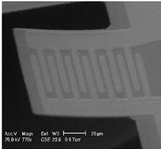
natural_image
Microscopic view of a microfluidic chip array with scale bar (20 μm) and imaging parameters (Acc.V, Magn, Det, WD, GSE 23.9, 0.9 Torr) shown at bottom
Figure 14. Scanning electron microscope image of the micro-piezoelectric cantilever with interdigitated electrodes. (Figure from Jeon et al 2005, © 2005, with permission from Elsevier.)
Similar to the research done by Zhou et al (2005), Jeon et al (2005) also examined the usefulness of operating a micropiezoelectric cantilever in the −33 bending mode through the use of interdigitated electrodes. A cantilever harvester having a length of 100 μm, a width of 60 μm, and a thickness of 0.48 μm was fabricated, as seen in figure 14. The resonant frequency of the cantilever was found to be 13.9 kHz, and when operated at resonance, a maximum tip displacement of 2.56 μm was observed. A maximum power output of 1.01 μW at 2.4 V occurred at resonance when a 5.2 M- load was applied to the system. Taking into consideration the on-chip circuitry as well as the cantilever itself, an energy density of 0.74 mWh cm−2 was obtained, which compares favorably to current lithium ion batteries. It was concluded that, through miniaturized power harvesters, wireless sensor networks can be both compact and self-powered.
In a study performed by Lee et al (2006), a novel fabrication technique was developed in order to create a piezoelectric MEMS power harvesting device with interdigitated electrodes operating in the −33 bending mode. The process was developed to help reduce the fabrication time and increase the quality of the piezoelectric device compared to existing techniques. A home-made jet printing PZT deposition chamber was developed in which 2 μm of PZT film could be deposited each pass. The technique was shown to be capable of depositing a high-quality PZT layer of up to 10 μm in minutes. Although the devices were successfully created, experimental testing was not performed, but should be investigated in the future.
In an effort towards achieving long term micro-power generation, Duggirala et al (2006) present a new form of piezoelectric power harvesting that involves radioactive thin films. The device developed, called a radioisotope-powered piezoelectric micro-power generator, utilizes radioactive materials to excite a piezoelectric cantilever beam. A thin-film radioactive source material is placed below the tip of a small cantilever beam that contains a piezoelectric patch near its base and a collector at the tip. As the radioactive source emits charged β-particles, the collector at the tip of the cantilever traps them. By charge conservation, the source and the collector build up opposite charges, leading to an electrostatic force between the two that draws them together. When the tip of the cantilever is drawn close enough to touch the radioactive thin film, the charge and the electrostatic force are neutralized and the cantilever begins to oscillate. The oscillatory motion of the beam stresses the piezoelectric patch and creates electrical energy. Experimentally, a 1 cm long generator was created and tested. The device was shown to provide a voltage of about 350 mV and a power of about 1.13 μW at the end of an oscillation into a load impedance of 90 k-. The device had an overall conversion efficiency of 3.7%. In a similar study, Duggirala et al (2004) also developed a self-powered acoustic transmitter using the same radioisotope-powered micro-power generator. Further details on this technology and potential applications are also presented by Lal et al (2005).
7. Self-powered sensors
The focus of many recent research studies involving piezoelectric power harvesting involves the development of self-powered sensors. With recent advances in wireless sensor technology, the need for energy sources that can harvest power from the environment and eliminate external power supplies and batteries is increasing. Studies have been conducted to explore the possibility of using piezoelectric power harvesting devices to provide energy to various types of sensors. In a study conducted by Ammar et al (2005), the necessary components for a self-powered wireless sensor node were discussed. The components included a microscale piezoelectric energy harvesting system, an energy harvesting circuit, a microprocessor, a MEMS sensor, onboard memory, an onboard clock, and a radio frequency transmitter. Additionally, the research investigated the feasibility of using a micro-scale piezoelectric generator to supply power to the circuit. Also, a self-powered microaccelerometer was proposed by Zhou et al (2005) in which a single piezoelectric cantilever was used as a sensor and a power harvester. Although the above research does not include the development of prototype self-powered sensors, many researchers have successfully created sensors that are powered by piezoelectric energy harvesting devices.
Roundy and Wright (2004) developed a small piezoelectric cantilever generator that was used to power a custom radio transmitter. The generator was designed with a 1 cm3 total volume, taking into consideration the size of most wireless sensor nodes. The radio transmitter consumed 10 mA of current at 1.2 V and was capable of transmitting a 1.9 GHz signal a distance of 10 m. Their study showed that, for excitation vibrations with a frequency of 120 Hz and an acceleration magnitude of , the piezoelectric generator was capable of charging a storage capacitor to a sufficient level at which the transmitter could be turned on. The radio transmitter demanded more energy than the piezoelectric device could generate, therefore, a low duty cycle of 1.6% was supported by the system.
The work of Arms et al (2005) focused on designing and fabricating a piezoelectric-powered wireless temperature and humidity sensor. A piezoelectric cantilever beam was used to harvest ambient vibrations to power the sensor and wireless data transmission circuitry. Figure 15 shows a photograph of the self-powered sensor. Research showed that, under low input vibrations on the order of and modest strain levels of around 200 , the cantilever was able to generate a relatively high amount of power. When combined with the wireless temperature and humidity sensor, it was found that the piezoelectric generator was capable of supplying enough energy to perpetually operate the sensor with low duty cycle wireless transmissions. Again, a low duty cycle was found because the piezoelectric harvester did not generate enough power to continually operate the sensor.
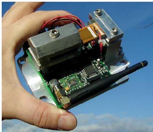
natural_image
Hand holding a small electronic circuit board with wires and components against a blue sky (no visible text or symbols)
Figure 15. Integrated piezoelectric vibration energy harvester and wireless temperature and humidity sensing node. (Figure from Arms et al 2005, reproduced with permission.)
In an effort to utilize piezoelectric energy generation in a biomechanical application, Platt et al (2005a), as discussed in a previous section of this paper, created a self-powered total knee replacement implant in which sensors encapsulated in the unit could provide in vivo diagnostic capabilities. A self-powered monitoring system is ideal for human body implants because of the long life expectation of the unit. Replacing batteries in implants requires additional surgery to remove and replace the battery. A simplified design is proposed by the research in which a focus is placed on the feasibility of piezoelectric power harvesting in creating a self-powered sensor rather than the complex details of implant design. A prototype implant was created which was capable of producing enough power to operate a PIC 16LF872 microprocessor. The microprocessor was programmed to turn on an LED indicator for a fixed period of time during the loading cycle. Tests showed that, when subjected to a 1300 N force, the system was able to illuminate the LED. In fact, approximately 225 of continuous power was generated by the piezoceramic and the PIC microprocessor only required 50 of power. This study has shown the ability of piezoelectric power harvesting systems to be used in human body implants to create in vivo self-powered sensors.
A fiber-based piezoelectric power harvesting device was used by Churchill et al (2003) to supply power to an adaptable wireless sensor node capable of recording signals from many different transducers and transmitting data wirelessly to a receiver. When subjected to a 180 Hz vibration that caused a strain of , the piezofiber-based harvesting system was able to power a microcontroller with onboard analog-to-digital conversion and wireless transmission capabilities for 250 ms. This proved to be enough time for the microcontroller to collect valid data from several sensors and transmit it four to seven times to ensure accuracy. In order for the microcontroller to operate, the piezofiber first charged a storage capacitor to a voltage of Once this voltage level was obtained, the microcontroller was activated and remained on until the voltage across the capacitor dropped to 2.5 V. Tests were conducted to measure the time interval between transmissions in order to find the duty cycle of the system. For moderate strain levels of 150 , the time it took for the capacitor to reach full charge and begin transmission was between 30 and 160 s, depending on the frequency of excitation. Higher excitation frequencies facilitated faster charging. Additionally, it was shown that the piezofiber generator was capable of harvesting 7.5 mW of power when a 180 Hz vibration causing 300 με was applied to the device.
Elvin et al (2003) studied the ability of a single piezoelectric element to act as both a sensor and a power supply to create a simplified self-powered sensor. Because the voltage generated by piezoceramic materials is proportional to the strain applied to the material, the device can be used as a strain sensor. Research was conducted to couple piezoelectric strain sensing and power harvesting into a single piezoelectric unit. A PVDF sensor and harvester was created and mounted to a beam that was to be monitored. The sensor was capable of measuring the strain in the beam which could then be used to identify damage in the beam in the form of a crack. Depending on the value of strain reported by the sensor, the crack depth was determined. Wireless transmission capabilities were incorporated into the system for communication purposes. When tested experimentally, the beam was subjected to a load causing a beam displacement of 2.2 mm at a frequency of 1 Hz. Sufficient energy was produced by the PVDF generator to allow radio frequency transmission of strain values within a single loading cycle. Additionally, the sensor data transmitted showed the ability to accurately predict the crack depth. The study successfully demonstrated the ability to use a single piezoelectric element as both a sensor and power supply, and function as a self-powered damage detection unit.
In a study focusing on self-powered machinery health monitoring, du Plessis et al (2005) investigated the possibility of harvesting energy from machinery vibrations with a piezoelectric cantilever to power a wireless health monitoring node. It was suggested that a sensor node be comprised of six components including an energy harvester, power conversion circuitry, a power storage module, a sensor, a processor, and a radio communications unit. The research involved analyzing an oil pump which was to be assessed using the health monitoring node. The natural frequency of the pump was found to be 130 Hz, and a piezoelectric cantilever was fabricated and tested near this resonance. The cantilever used was a quick pack QP21B. Under an excitation producing a strain of 700 με at 100 Hz, the cantilever was able to produce 2.8 mW of power. Experiments were also conducted to test the durability of the quick pack. At a strain of 700 at 100 Hz, the quick pack encountered cycles at which the test was terminated. This study proved the ability of a piezoelectric cantilever to produce enough power and withstand enough strain to be used in a machinery health monitoring sensor node. This research was continued by Discenzo et al (2006), who developed a self-powered sensor node capable of scavenging energy from the oil pump. The node was programmed to sample three analog inputs including the voltage level generated from the piezoelectric generator, the state of charge on the storage capacitor bank, and data from an accelerometer. This information was stored in the local processor memory and also transmitted to a remote receiver. Instead of a quick pack cantilever, a T220-A4 from Piezo Systems Inc. was used. The resonant frequency of the cantilever was tuned to match the 130 Hz operational frequency of the oil pump. The sensor node was programmed to hibernate for one hour while collecting energy from the piezoelectric cantilever, then turn on, collect data, and transmit the data collected. The sensor node was installed on an oil pump in an oil tanker ship and left operating for four months. At the end of the four months, over 8000 data files were captured by the sensor. This study shows a successful application of providing power to sensors using piezoelectric materials.
8. Performance of piezoelectric versus other materials
Harvesting energy from ambient vibrations is a topic that has recently attracted much attention. Many studies have been conducted to investigate the possibility of harvesting vibration energy with piezoelectric materials. There are, however, four basic methods by which vibration energy can be converted into electrical energy. These methods include harvesting with piezoelectric, electromagnetic and electrostatic generators, and each method has received attention by researchers. Electromagnetic power harvesters contain a magnet that oscillates in a coil causing current to flow in the coil. Electrostatic generators contain two conductors, separated by a dielectric, that vibrate relative to each other, behaving like a capacitor. The following studies compare the advantages and disadvantages of each method of energy harvesting.
Roundy et al (2003) compared the three basic vibration energy harvesting methods. A qualitative comparison of each conversion method is given. It was explained that piezoelectric generators require no voltage source to harvest energy, but that they are more difficult to integrate into microsystems. Electrostatic generators are easier to integrate into microsystems, but require a separate voltage source to operate. Electromagnetic generators do not require a voltage to operate, but they output relatively low voltages. Upon discovering these advantages and disadvantages, the researchers decided to focus only on electrostatic and piezoelectric power harvesting methods. After modeling and experimentally testing a cantilever piezoelectric harvester and an electrostatic harvester, it was found that piezoelectric converters are capable of producing more power per unit volume than electrostatic converters. Again, it is noted that piezoelectrics require no voltage, but electrostatics are more suited for integration into microsystems. Roundy (2005) continued the comparative study conducted in 2003. A more in-depth study of all three energy conversion methods was presented and additional conclusions were made. It was found that the best technology needs to be selected based upon the environmental conditions and the physical constraints of the system. Some considerations are as follows. Piezoelectric generators produce high voltages and low currents. Also, for both piezoelectric and electrostatic generators, current generation decreases as the size of the device decreases. Electrostatic generators require oscillations at a magnitude of hundreds of microns while maintaining a minimum capacitive gap of about 0.5 μm or less to provide comparable power levels to other technologies, which creates implementation issues. Finally, electromagnetic generators generally produce low voltages and the voltage output decreases as the size of the generator decreases.
Another study comparing the performance of piezoelectric, electromagnetic, and electrostatic energy generation methods was conducted by Sterken et al (2004). Each power generation technique was modeled mathematically and then compared. It was proposed that, under many conditions, all three methods could be used to convert vibration energy into electrical energy. Each method, however, operates best under certain circumstances. It was concluded that electromagnetic conversion is best suited for large systems in which the power harvesting device itself can be large. Electrostatic generators, on the other hand, are best suited for very small systems due to the small gap required between capacitor plates. Piezoelectric converters are capable of harvesting energy for all size levels: however, the maximum power generation capability of piezoelectrics is lower than that of electromagnetic or electrostatic systems. This study helps allow a designer to select an appropriate power harvesting method based on the size constraints imposed by the application.
A specific area in which different energy conversion methods have been compared lies in human powered applications. Poulin et al (2004) have compared the ability of both piezoelectric and electromagnetic power harvesting methods to harvest power from human movement to power portable electronic devices. The electromagnetic system studied was composed of a magnet moving in translation through a coil. The piezoelectric system was made up of a piezoceramic bar embedded at one end and free at the other. The research presents an analytical comparison of both systems. Some conclusions were made when comparing typically sized systems of each type. The maximum volumetric power output of both systems was relatively close, however, the resonant frequency of the electromagnetic system was on the order of a few hertz, where the resonant frequency of the piezoelectric system was on the order of a few hundred kilohertz. Additionally, the matching load resistance of both systems varied considerable. The matching load for the electromagnetic system was in the k- range, and the matching load for the piezoelectric system was in the Mrange. Lastly, it was concluded that a piezoelectric system yields a high power density, making it attractive for micro-scale applications, and electromagnetic systems are better suited for macro-scale applications.
A similar study involving the comparison of power harvesting methods in human powered applications was presented by Niu et al (2004). Piezoelectric, electromagnetic, and electrostatic configurations were compared as a means of harvesting energy from heel strike during walking. Upon investigating the three methods, it was determined that electrostatic generation would not be useful in heel strike energy conversion because of the additional voltage supply that it requires to convert mechanical energy to electrical energy. Also, it was stated that electrostatic devices only outperform electromagnetic devices when very small displacements are involved. When analyzing piezoelectric devices for heel strike energy harvesting, it was found that piezoelectrics in compression mode do not produce significant power outputs when subjected to a typical heel strike excitation. The bending mode was also investigated for a piezoelectric device, but it was found that a cantilever beam mounted in a shoe is unable to utilize the strain imposed by heel strike to harvest useful energy. In analyzing electromagnetic systems, it was noted that electromagnetic devices often have low efficiencies when subjected to low frequency vibrations, such as those found in heel strike excitation. The possibility of converting low frequency heel strike excitation into higher frequency rotary motion was discussed. This conversion could allow an electromagnetic device to work efficiently in heel strike applications. A major drawback, however, of electromagnetic systems is their relatively large weight when compared to piezoelectric systems. In comparing the two types of power harvesting systems, it was found that piezoelectric devices have limited applications in heel strike environments, and that electromagnetic devices, although inefficient under low excitations, are potentially better candidates if heel strike excitation can be translated into rotational excitation.
9. Concluding remarks
Power harvesting is the key to providing fully self-powered systems in the growing portable and wireless electronics market. While this field has seen a number of schemes for harvesting ambient energy sources, piezoelectric materials can be easily incorporated into many systems that are subjected to dynamic energy. Although the design specifications and power harvesting capabilities of most piezoelectric energy harvesting systems are not trivial and require much attention, any vibrating host presents the possibility of harvesting energy. The application of piezoelectric materials in power harvesting systems contains many variables which can be manipulated to obtain electrical energy from ambient vibration such that wireless electronics can be operated in a self-powered manner. A number of these factors have been detailed in the literature, which now acts as a comprehensive base for future researchers to build on.
A majority of the latest research has focused on improving the efficiency of piezoelectric power harvesting devices through physical and geometrical configuration, as well as adaptive circuitry and energy removal techniques. The challenge facing many researchers remains the difference between the energy consumption of the electronics used to store the harvested energy and the energy generation capabilities of the power harvesting device. The improvement of energy generation and storage methods combined with the decreasing power requirements of today’s electronics help bring the concept of creating self-powered electronics closer to reality.
Much of the research up to this point has focused on the characterization of the power harvesting medium rather than the development of complete self-powered devices. The authors of this article feel that the future of power harvesting is in the development of complete systems (power harvesting, storage, and application circuitry combined) that can be readily implemented. Preliminary research has been conducted, for example, on a complete autonomous sensing unit that incorporates structural health monitoring and power harvesting technologies into a single, self-powered device (Inman and Grisso 2006). Further development of such systems will facilitate the progression of power harvesting methods from a pure research topic to a useable technology in practical devices.
References
Ammar Y, Buhrig A, Marzencki M, Charlot B, Basrour S, Matou K and Renaudin M 2005 Wireless sensor network node with asynchronous architecture and vibration harvesting micro power generator Proc. 2005 Joint Conf. on Smart Objects and Ambient ibeuntelligence: Innovative Context-Aware Services: Usages and Technologies (Grenoble) pp 287–92
Anderson T A and Sexton D W 2006 A vibration energy harvesting sensor platform for increased industrial efficiency Proc. Smart Structures and Materials Conf.; Proc. SPIE 6174 61741Y
Arms S W, Townsend C P, Churchill D L, Galbreath J H and Mundell S W 2005 Power management for energy harvesting wireless sensors Proc. Smart Structures and Materials Conf.; Proc. SPIE 5763 267–75
Ayers J P, Greve D W and Oppenheim I J 2003 Energy scavenging for sensor applications using structural strains Proc. Smart Structures and Materials Conf.; Proc. SPIE 5057 364–75
Badel A, Guyomar D, Lefeuvre E and Richard C 2005 Efficiency enhancement of a piezoelectric energy harvesting device in pulsed operation by synchronous charge inversion J. Intell. Mater. Syst. Struct. 16 889–901
Baker J, Roundy S and Wright P 2005 Alternative geometries for increasing power density in vibration energy scavenging for wireless sensor networks Proc. 3rd Int. Energy Conversion Engineering Conf. (San Francisco, CA, Aug.) pp 959–70
Bayrashev A, Robbins W P and Ziaie B 2004 Low frequency wireless powering of microsystems using piezoelectric–magnetostrictive laminate composites Sensors Actuators A 114 244–9
Bent A A, Hagood N W and Rodgers J P 1995 Anisotropic actuation with piezoelectric fiber composites J. Intell. Mater. Syst. Struct. 6 338–49
Cho J, Anderson M, Richards R, Bahr D and Richards C 2005a Optimization of electromechanical coupling for a thin-film PZT membrane: I. modeling J. Micromech. Microeng. 15 1797–803
Cho J, Anderson M, Richards R, Bahr D and Richards C 2005b Optimization of electromechanical coupling for a thin-film PZT membrane: II. experiment J. Micromech. Microeng. 15 1804–9
Churchill D L, Hamel M J, Townsend C P and Arms S W 2003 Strain energy harvesting for wireless sensor networks Proc. Smart Struct. and Mater. Conf.; Proc. SPIE 5055 319–27
Cornwell P J, Goethal J, Kowko J and Damianakis M 2005 Enhancing power harvesting using a tuned auxiliary structure J. Intell. Mater. Syst. Struct. 16 825–34
Danak A D, Yoon H S and Washington G N 2003 Optimization of electrical output in response to mechanical input in piezoceramic laminated shells Proc. ASME Int. Mechanical Engineering Congr. (Washington, DC, Nov.) pp 309–15
Discenzo F M, Loparo K A, Cassar H and Chung D 2006 Machinery condition monitoring using wireless self-powered sensor nodes Proc. 24th Int. Modal Analysis Conf. (St. Louis, MO, Jan.–Feb.)
du Plessis A J, Huigsloot M J and Discenzo F D 2005 Resonant packaged piezoelectric power harvester for machinery health monitoring Proc. Smart Struct. Mater. Conf.; Proc. SPIE 5762 224–35
Duggirala R, Li H and Lal A 2004 An autonomous self-powered acoustic transmitter using radioactive thin films IEEE Ultrason. Symp. 2 1318–21
Duggirala R, Polcawich R, Zakar E, Dubey M, Li H and Lal A 2006 MEMS radioisotope-powered piezoelectric power generator MEMS: Proc. IEEE 19th Int. Conf. on Micro Electro Mechanical Systems (Istanbul) pp 94–97
Elvin N, Elvin A and Choi D H 2003 A self-powered damage detection sensor J. Strain Anal. Eng. Des. 38 115–24
Ericka M, Vasic D, Costa F, Poulin G and Tliba S 2005 Energy harvesting from vibration using a piezoelectric membrane J. Physique. Coll. IV 128 187–93
Glynne-Jones P, Tudor M J, Beeby S P and White N M 2004 An electromagnetic, vibration-powered generator for intelligent sensor systems Sensors Actuators A 110 344–9
Gonz´alez J L, Rubio A and Moll F 2002 Human powered piezoelectric batteries to supply power to wearable electronic devices Int. J. Soc. Mater. Eng. Resources 10 34–40
Guan M and Liao W H 2006 On the energy storage devices in piezoelectric energy harvesting Proc. Smart Structures and Materials Conf.; Proc. SPIE 6169 61690C
Gurav S P, Kasyap A, Sheplak M, Cattafesta L, Haftka R T, Goosen J F L and Van Keulen F 2004 Uncertainty-based design optimization of a micro piezoelectric composite energy reclamation device Proc. 10th AIAA/ISSMO Multidisciplinary Analysis and Optimization Conf. pp 3559–70
Guyomar D, Badel A, Lefeuvre E and Richard C 2005 Toward energy harvesting using active materials and conversion improvement by nonlinear processing IEEE Trans. Ultrason. Ferroelectr. Freq. Control 52 584–94
Han J, Von Jouanne A, Le T, Mayaram K and Fiez T S 2004 Novel power conditioning circuits for piezoelectric micro power generators Proc. 19th Ann. IEEE Applied Power Electronics Conf. and Exposition Conf. pp 1541–6
Inman D J and Grisso B L 2006 Towards autonomous sensing Proc. Smart Structures and Materials Conf.; Proc. SPIE 6174 61740T
Jeon Y B, Sood R, Jeong J H and Kim S G 2005 MEMS power generator with transverse mode thin film PZT Sensors Actuators A 122 16–22
Jiang S, Li X, Guo S, Hu Y, Yang J and Jiang Q 2005 Performance of a piezoelectric bimorph for scavenging vibration energy Smart Mater. Struct. 14 769–74
Johnson T J, Charnegie D, Clark W W, Buric M and Kusic G 2006 Energy harvesting from mechanical vibrations using piezoelectric cantilever beams Proc. Smart Structures and Materials Conf.; Proc. SPIE 6169 61690D
Kim H W, Batra A, Priya S, Uchino K, Markley D, Newnham R E and Hofmann H F 2004 Energy harvesting using a piezoelectric ‘cymbal’ transducer in dynamic environment Japan. J. Appl. Phys. 43 6178–83
Kim H W, Priya S, Uchino K and Newnham R E 2005 Piezoelectric energy harvesting under high pre-stressed cyclic vibrations J. Electroceram. 15 27–34
Kim S, Clark W W and Wang Q M 2005a Piezoelectric energy harvesting with a clamped circular plate: analysis J. Intell. Mater. Syst. Struct. 16 847–54
Kim S, Clark W W and Wang Q M 2005b Piezoelectric energy harvesting with a clamped circular plate: experimental study J. Intell. Mater. Syst. Struct. 16 855–63
Kornbluh R D, Pelrine R, Pei Q, Heydt R, Stanford S, Oh S and Eckerle J 2002 Electroelastomers: applications of dielectric elastomer transducers for actuation, generation, and smart structures Proc. Smart Structures and Materials Conf.; Proc. SPIE 4698 254–70
Kymissis J, Kendall D, Paradiso J and Gershenfeld N 1998 Parasitic power harvesting in shoes 2nd IEEE Int. Conf. on Wearable Computing (August) pp 132–6
Lal A, Duggirala R and Li H 2005 Pervasive power: a radioisotope-powered piezoelectric generator IEEE Pervasive Comput. 4 53–61
Lee B S, He J J, Wu W J and Shih W P 2006 MEMS generator of power harvesting by vibrations using piezoelectric cantilever
beam with digitate electrode Proc. Smart Structures and Materials Conf.; Proc. SPIE 6169 61690B
Lee C S, Joo J, Han S and Koh S K 2004 Multifunctional transducer using poly(vinylidene fluoride) active layer and highly conducting poly(3,4-ethylenedioxythiophene) electrode: actuator and generator Appl. Phys. Lett. 85 1841–3
Lee C S, Joo J, Han S, Lee J H and Koh S K 2005 Poly(vinylidene fluoride) transducers with highly conducting poly(3,4-ethylenedioxythiophene) electrodes Proc. Int. Conf. on Science and Technology of Synthetic Metals vol 152 pp 49–52
Lefeuvre E, Badel A, Benayad A, Lebrun L, Richard C and Guyomar D 2005a A comparison between several approaches of piezoelectric energy harvesting J. Physique Coll. 128 177–86
Lefeuvre E, Badel A, Richard C and Guyomar D 2004 High performance piezoelectric vibration energy reclamation Proc. Smart Structures and Materials Conf.; Proc. SPIE 5390 379–87
Lefeuvre E, Badel A, Richard C and Guyomar D 2005b Piezoelectric energy harvesting device optimization by synchronous electric charge extraction J. Intell. Mater. Syst. Struct. 16 865–76
Lefeuvre E, Badel A, Richard C, Petit L and Guyomar D 2006 A comparison between several vibration-powered piezoelectric generators for standalone systems Sensors Actuators A 126 405–16
Lesieutre G 1998 Vibration damping and control using shunted piezoelectric materials Shock Vib. Digest 30 188–95
Lesieutre G A, Ottman G K and Hofmann H F 2004 Damping as a result of piezoelectric energy harvesting J. Sound Vib. 269 991–1001
Lu F, Lee H P and Lim S P 2004 Modeling and analysis of micro piezoelectric power generators for micro-electromechanical-systems applications Smart Mater. Struct. 13 57–63
Mateu L, Fonellosa F and Moll F 2003 Electrical characterization of a piezoelectric film-based power generator for autonomous wearable devices Proc. 18th Conf. on Design of Circuits and Integrated Systems (Ciudad Real) pp 677–82
Mateu L and Moll F 2005 Optimum piezoelectric bending beam structures for energy harvesting using shoe inserts J. Intell. Mater. Syst. Struct. 16 835–45
Mitcheson P D, Miao P, Stark B H, Yeatman E M, Holmes A S and Green T C 2004 MEMS electrostatic micro-power generator for low frequency operation Sensors Actuators A 115 523–9
Mohammadi F, Khan A and Cass R B 2003 Power generation from piezoelectric lead zirconate titanate fiber composites Proc. Materials Research Symp. p 736
Mossi K, Green C, Ounaies Z and Hughes E 2005 Harvesting energy using a thin unimorph prestressed bender: geometrical effects J. Intell. Mater. Syst. Struct. 16 249–61
Ng T H and Liao W H 2004 Feasibility study of a self-powered piezoelectric sensor Proc. Smart Structures and Materials Conf.; Proc. SPIE 5389 377–88
Ng T H and Liao W H 2005 Sensitivity analysis and energy harvesting for a self-powered piezoelectric sensor J. Intell. Mater. Syst. Struct. 16 785–97
Niu P, Chapman P, Riemer R and Zhang X 2004 Evaluation of motions and actuation methods for biomechanical energy harvesting Proc. IEEE 35th Annual Power Electronics Specialists Conf. (Aachen) pp 2100–6
Ottman G K, Hofmann H F and Lesieutre G A 2002 Optimized piezoelectric energy harvesting circuit using step-down converter in discontinuous conduction mode Proc. IEEE 33rd Annual Power Electronics Specialists Conf. (Cairns, Queensland, June) 4 pp 1988–94
Paradiso J A and Starner T 2005 Energy scavenging for mobile and wireless electronics IEEE Pervasive Comput. 4 18–27
Platt S R, Farritor S and Haider H 2005a On low-frequency electric power generation with PZT ceramics IEEE/ASME Trans. Mechatronics 10 240–52
Platt S R, Farritor S and Haider H 2005b The use of piezoelectric ceramics for electric power generation within orthopedic implants IEEE/ASME Trans. Mechatronics 10 455–61
Pobering S and Schwesinger N 2004 A novel hydropower harvesting device Proc. 2004 Int. Conf. on MEMS, NANO and Smart Systems (Banff, AL, Aug.) pp 480–5
Poulin G, Sarraute E and Costa F 2004 Generation of electrical energy for portable devices: comparative study of an electromagnetic and a piezoelectric system Sensors Actuators A 116 461–71
Priya S 2005 Modeling of electric energy harvesting using piezoelectric windmill Appl. Phys. Lett. 87 184101
Priya S, Chen C T, Fye D and Zahnd J 2005 Piezoelectric windmill: a novel solution to remote sensing Japan. J. Appl. Phys. 2 44 L104–7
Rastegar J, Pereira C and Nguyen H L 2006 Piezoelectric-based power sources for harvesting energy from platforms with low frequency vibration Proc. Smart Structures and Materials Conf.; Proc. SPIE 6171 617101
Renaud M, Sterken T, Fiorini P, Puers R, Baert K and Van Hoof C 2005 Scavenging energy from human body: design of a piezoelectric transducer Proc. 13th Int. Conf. on Solid-State Sensors and Actuators and Microsystems (Seoul, June) pp 784–7
Richards C D, Anderson M J, Bahr D F and Richards R F 2004 Efficiency of energy conversion for devices containing a piezoelectric component J. Micromech. Microeng. 14 717–21
Roundy S 2005 On the effectiveness of vibration-based energy harvesting J. Intell. Mater. Syst. Struct. 16 809–23
Roundy S, Leland E S, Baker J, Carleton E, Reilly E, Lai E, Otis B, Rabaey J, Wright P K and Sundararajan V 2005 Improving power output for vibration-based energy scavengers IEEE Pervasive Comput. 4 28–36
Roundy S and Wright P K 2004 A piezoelectric vibration based generator for wireless electronics Smart Mater. Struct. 13 1131–42
Roundy S, Wright P K and Rabaey J 2003 A study of low level vibrations as a power source for wireless sensor nodes Comput. Commun. 26 1131–44
Roundy S and Zhang Y 2005 Toward self-tuning adaptive vibration based micro-generators Smart Materials, Nano- and Micro-Smart Systems (Sydney, Dec.)
Sch¨onecker A J, Daue T, Br¨uckner B, Freytag C, H¨ahne L and R¨odig T 2006 Overview on macro fiber composite applications Proc. Smart Structures and Materials Conf.; Proc. SPIE 6170 61701K
Shahruz S M 2006a Design of mechanical bandpass filters for energy scavenging J. Sound Vib. 292 987–98
Shahruz S M 2006b Limits of performance of mechanical band-pass filters used in energy scavenging J. Sound Vib. 293 449–61
Shenck N S and Paradiso J A 2001 Energy scavenging with shoe-mounted piezoelectrics IEEE Micro 21 30–42
Sodano H A, Inman D J and Park G 2005a Comparison of piezoelectric energy harvesting devices for recharging batteries J. Intell. Mater. Syst. Struct. 16 799–807
Sodano H A, Inman D J and Park G 2005b Generation and storage of electricity from power harvesting devices J. Intell. Mater. Syst. Struct. 16 67–75
Sodano H A, Lloyd J and Inman D J 2004a An experimental comparison between several active composite actuators for power generation Proc. Smart Structures and Materials Conf.; Proc. SPIE 5390 370–8
Sodano H A, Park G and Inman D J 2004b A review of power harvesting using piezoelectric materials Shock Vib. Digest 36 197–206
Sodano H A, Park G and Inman D J 2004c Estimation of electric charge output for piezoelectric energy harvesting Strain 40 49–58
Sohn J W, Choi S B and Lee D Y 2005 An investigation on piezoelectric energy harvesting for MEMS power sources J. Mech. Eng. Sci. 219 429–36
Starner T and Paradiso J 2004 Human generated power for mobile electronics Low Power Electronics Design ed Piguet C (Boca Raton, FL: CRC Press) chapter 45
Sterken T, Baert K, Van Hoof C, Puers R, Borghs G and Fiorini P 2004 Comparative modelling for vibration scavengers Proc. IEEE Sensors Conf. (Vienna, Oct.) pp 1249–52
Tayahi M B, Johnson B, Holtzman M and Cadet G 2005 Piezoelectric materials for powering remote sensors Proc. IEEE 24th Int. Performance, Computing, and Communications Conf. (Phoenix, AZ, April) pp 383–6
Taylor G W, Burns J R, Kammann S M, Powers W B and Welsh T R 2001 The energy harvesting eel: a small subsurface ocean/river power generator IEEE J. Oceanic Eng. 26 539–47
Wilkie W K, Bryant R G, High J W, Fox R L, Hellbaum R F, Jalink A, Little B D and Mirick P H 2000 Low-cost piezocomposite actuator for structural control applications Proc. 7th Int. Symp. on Smart Structures and Materials; Proc. SPIE 3991 323–34
Williams C B and Yates R B 1995 Analysis of a micro-electric generator for microsystems Transducers 95/Eurosensors IX vol 1 pp 369–72
Wu W J, Chen Y Y, Lee B S, He J J and Peng Y T 2006 Tunable resonant frequency power harvesting devices Proc. Smart Structures and Materials Conf.; Proc. SPIE 6169 61690A
Yang J, Zhou H, Hu Y and Jiang Q 2005 Performance of a piezoelectric harvester in thickness-stretch mode of a plate IEEE Trans. Ultrason. Ferroelectr. Freq. Control 52 1872–6
Yoon H S, Washington G and Danak A 2005 Modeling, optimization, and design of efficient initially curved piezoceramic unimorphs for energy harvesting applications J. Intell. Mater. Syst. Struct. 16 877–88
Zhou W, Liao W H and Li W J 2005 Analysis and design of a self-powered piezoelectric microaccelerometer Proc. Smart Structures and Materials Conf.; Proc. SPIE 5763 233–40