Topical Review
A review of energy harvesting using piezoelectric materials: state-of-the-art a decade later (2008–2018)
Mohsen Safaei1 , Henry A Sodano2 and Steven R Anton1
1 Department of Mechanical Engineering, Tennessee Technological University, Cookeville, TN 38505, United States of America
2 Department of Aerospace Engineering, University of Michigan, Ann Arbor, MI 48109, United States of America
E-mail: santon@tntech.edu
Received 4 January 2019, revised 1 May 2019
Accepted for publication 30 July 2019
Published 22 October 2019

CrossMark
Abstract
Energy harvesting technologies have been explored by researchers for more than two decades as an alternative to conventional power sources (e.g. batteries) for small-sized and low-power electronic devices. The limited life-time and necessity for periodic recharging or replacement of batteries has been a consistent issue in portable, remote, and implantable devices. Ambient energy can usually be found in the form of solar energy, thermal energy, and vibration energy. Amongst these energy sources, vibration energy presents a persistent presence in nature and manmade structures. Various materials and transduction mechanisms have the ability to convert vibratory energy to useful electrical energy, such as piezoelectric, electromagnetic, and electrostatic generators. Piezoelectric transducers, with their inherent electromechanical coupling and high power density compared to electromagnetic and electrostatic transducers, have been widely explored to generate power from vibration energy sources. A topical review of piezoelectric energy harvesting methods was carried out and published in this journal by the authors in 2007. Since 2007, countless researchers have introduced novel materials, transduction mechanisms, electrical circuits, and analytical models to improve various aspects of piezoelectric energy harvesting devices. Additionally, many researchers have also reported novel applications of piezoelectric energy harvesting technology in the past decade. While the body of literature in the field of piezoelectric energy harvesting has grown significantly since 2007, this paper presents an update to the authors’ previous review paper by summarizing the notable developments in the field of piezoelectric energy harvesting through the past decade.
Keywords: energy harvesting, piezoelectricity, piezoelectric materials
(Some figures may appear in colour only in the online journal)

Original content from this work may be used under the terms of the Creative Commons Attribution 3.0 licence. Any
further distribution of this work must maintain attribution to the author(s) and the title of the work, journal citation and DOI.
1. Introduction
A comprehensive review on piezoelectric energy harvesting technologies was performed by the authors in 2007 [1]. However, many novel approaches have been developed since 2007 in order to enhance material properties, transducer architectures, electrical interfaces, predictive models, and the application space of piezoelectric energy harvesting devices. This article, as an extension to the authors’ former review article [1], summarizes the published work on the topic of piezoelectric energy harvesting over the past 11 years (from 2008 to 2018). It should be noted that a vast amount of work has been presented on piezoelectric energy harvesting in this timespan, which precludes citation of every work, therefore, this article attempts to provide a concise review of the most impactful studies in the field. Furthermore, cited works are primarily restricted to peer-reviewed journal publications in order to ensure quality.
Recent improvements in the development of small-sized, low-power, portable, and remote devices have led to the introduction of nonconventional power sources during the past two decades. Batteries are considered conventional energy sources yet suffer from several limitations, such as limited lifespan and power efficiency as well as limited energy storage capacity, which necessitates frequent recharging [2]. The concept of harvesting energy from ambient sources to eliminate the need for batteries or to extend their life has become a major focus of researchers. Energy harvesting has the potential to extend the working life of electronics and offers particular application to inaccessible electronics or those subject to costly maintenance, such as sensory nodes in remote locations, implanted health trackers, biomedical devices [3, 4], and large-scale sensor networks [5–7]. Energy harvesting can be defined as the direct transformation of ambient energy (mechanical, solar, thermal, wind, fluid flow, etc.) to electrical energy using a particular material or transduction mechanism. Several energy harvesting materials exist, each with a unique conversion mechanism that can be employed for energy harvesting. Some of the most common energy harvesting materials include photovoltaics (solar panels) to convert solar energy to electric energy [8–14], thermoelectrics (thermoelectric generators) to convert temperature differentials into electrical energy [15–19], and electromechanical transducers (piezoelectrics, electrostatic generators) to convert mechanical vibration energy into electrical energy [20–25]. Mechanical vibration energy is common in many environments where energy harvesting can be beneficial. Vibration energy may exist due to the surrounding environment (i.e. wind, fluid flow), and also due to operational conditions (e.g. rotating machinery). The existence of multiple sources of vibration energy is advantageous for vibration-based energy harvesting methods as opposed to other techniques by decoupling stochastic environmental effects from the performance of the energy harvesting system.
The conversion of dynamic mechanical energy into electrical energy using piezoelectric materials is typically called piezoelectric energy harvesting. Piezoelectric energy harvesting of ambient vibration usually focuses on harvesting low-level energy, on the order of microwatts to milliwatts, to power low-power electronics. When compared to thermal and solar energy harvesters, which can generate hundreds of watts, piezoelectric materials usually operate at much lower energy levels. Some of the advantages of piezoelectric transduction over thermal and solar harvesting include the fact that ambient vibrations are often persistent due to operational conditions of a system, therefore, do not rely on unsteady and unpredictable environmental conditions which can fluctuate in time. Furthermore, piezoelectric harvesters are useful in situations where thermal and solar energy is absent, and are particularly useful in embedded systems. It is reported that the worldwide annual revenue of piezoelectric devices has been increased from $22 billion in 2012 to $37 billion in 2017, which shows a dramatic increase in the demand and application of piezoelectric systems [26].
Some examples of environments where piezoelectric vibration energy harvesting can be used include civil infrastructure such as buildings and bridges [27, 28], aerospace systems [29–33], and the human body [34, 35]. Generally, vibratory energy can be converted to usable power using piezoelectric, electrostatic [36–38], electromagnetic [39–42], magnestrictive [43–47], and triboelectric convertors [48–53]. The advantages of piezoelectric generators over the other methods include their inherent transduction capacity, the preservation of efficiency as scale is reduced, higher power density, and capacity to function in high frequency applications [54]. In order to capture vibration energy from a structure, a piezoelectric harvester must be attached to the host structure so that the vibratory energy is effectively transferred from the host to the harvester. Such a mechanical interface can be established in many ways, however, the optimal choice is usually dictated by the design constraints and characteristics of the overall system.
Given the fact that most piezoelectric harvesting systems operate at the microwatt to milliwatt scale, the most common application of piezoelectric energy harvesting is to provide energy for low-power electronics including embedded electronics, implantable biomedical devices, wireless sensor nodes, and portable electronics. Piezoelectric harvesting systems can provide a permanent, autonomous power source that does not need replacement or maintenance. Compared to traditional energy sources, like batteries, autonomous operation can reduce costs associated with battery replacement. Furthermore, autonomous power supplies allow electronic devices to be embedded into structures or placed in remote locations. With recent growth in low-power electronics (e.g. wireless sensors, microelectronics), piezoelectric energy harvesting has drawn significant attention in the research community over the past decade. The purpose of this paper is to provide a summary of advancements made in the field of piezoelectric energy harvesting over the past decade. This review is organized as follows; section 2 discusses various piezoelectric materials and configurations presented in the literature to harvest vibration energy from ambient sources. In addition, the most exploited mathematical models as well as power conditioning circuits for piezoelectric generators are briefly discussed in this section. Section 3 details recently proposed devices and applications for energy harvesting using piezoelectric transducers including power scavenging from fluid sources, the human body, animals, infrastructure, and vehicles, and well as multifunctional and multi-source harvesting, and other applications. Finally, section 4 provides the authors’ concluding remarks.
2. Piezoelectric energy harvesting materials and methods
Since the discovery of ferroelectric materials such as barium titanate and lead zirconate titanate (PZT), piezoelectricity has been observed in a myriad of synthetic materials as researchers have continuously developed piezoelectric materials with various electromechanical, mechanical, and thermal properties. In this section, several piezoelectric materials with enhanced performance compared to traditional piezoelectric materials are briefly discussed, and different transducer configurations developed for piezoelectric energy harvesting are reviewed. Additionally, a summary of common mathematical models and conditioning circuitry is provided.
2.1. Piezoelectric materials
Many piezoelectric materials have been developed over the past century, however the most common piezoelectric material is the perovskite lead zirconate titanate, a polycrystalline monolithic piezoelectric ceramic known as PZT that is often doped with niobium or lanthanum to form soft and hard piezoelectric materials, respectively. Piezoelectric ceramics, or piezoceramics, have found widespread use in sensors and actuators due to their direct coupling which enables operation without bias voltages, and their ability to output large voltages on the order of 50 V to 100 V (although currents are typically quite small, in the nanoamp to milliamp range). While PZT is the most common material, it contains lead and, therefore, the development of new compositions is a large and ongoing research thrust [55–58]. Recently, Gao et al in 2018 [59] developed a PNN-PZT ceramic with a remarkably high coupling coefficient of 1753 pC N−1 , which is much higher than conventional PZT ceramics. While piezoelectric ceramics are relatively affordable and provide good coupling, they are brittle and have a high density. Given the growing application of piezoelectric ceramics in microelectromechanical systems (MEMS), PZT thin films have been developed to capitalize upon the small scale to achieve flexibility [60], as well as the use of grain texturing [61] and epitaxial thin films on substrates [62] to improve coupling. Although methods for fabricating high quality piezoelectric films are available, a vast amount of ongoing research is being performed on optimized material deposition for 3D transducers, developing lower temperature fabrication methods and alternative substrate materials, and improving texturing of electrodes [63]. Porous piezoelectric materials also present higher hydrostatic piezoelectric strain and voltage coefficients compared to dense piezoelectrics, which makes them an excellent candidate for hydrostatic sensors, such as active and passive sound navigation and ranging (SONAR) [64–66]. Furthermore, in order to provide compliant piezoelectric materials, piezoelectric polymers have been developed, which include polyvinylidene fluoride (PVDF), another common piezoelectric material. While piezoelectric polymers are lightweight and flexible, their coupling is considerably lower than their ceramic counterparts [474]. In an effort by Pan et al in 2015 [67], preparation of PVDF material using a near field electrospinning method was suggested to enhance the coupling coefficient of these materials by an order of two. Recently, Harstad et al in 2017 [68] developed a new approach to improve the coupling of PVDF polymers by increasing the β phase percentage in the material composition (note, the coupling coefficient of PVDF materials is directly proportional to the β phase percentage). The enhancement is achieved by synthesizing nanocomposite using a phase-inversion method. The majority of piezoelectric energy harvesting transducer materials aside from PZT and PVDF can be categorized into five groups including piezoelectric single crystals, lead-free piezoelectrics, high temperature piezoelectrics, piezoelectric nanocomposites, and piezoelectret foams.
2.1.1. Piezoelectric single crystals. Piezoelectric single crystals were developed to achieve superior coupling through uniform dipole alignment and outperform polycrystalline piezoceramics in many applications. The electromechanical coupling coefficient of single crystal piezoelectric materials can be significantly greater than monolithic materials, and in the highest performance materials can be several times greater than PZT [69–72]. The drawback to these materials is their higher cost, reduced toughness, and high damping [73]. However, despite these drawbacks, researchers have begun to incorporate piezoelectric single crystals in vibration-based energy harvesting systems to leverage their high electromechanical coupling.
Ren et al in 2010 [74] fabricated and tested a shear-based PMN-PT unimorph cantilever that was subjected to sinusoidal base excitation. The unimorph consisted of brass shim with a bonded wafer and a tip mass of 0.5 g, and was able to generate 4.16 mW of power under a cyclic excitation force of 0.05 N at 60 Hz with a peak voltage output measured at 91.2 V. When compared to a similar PMN-PT cantilever operating in the mode, it was found that the shear mode device could generate considerably more power (approximately eight times more power). In 2009, Mathers et al [75] studied the application of interdigitated electrodes applied to a micro-scale PMN-PT cantilever-based energy harvester. The device had dimensions of with a PMN-PT beam, a polydimethylsiloxane (PDMS) polymer coating, a PDMS tip mass, and interdigitated electrodes. Under excitation at its natural frequency of 1340 Hz and a displacement of 1 mm at the clamp, the device produced approximately 0.3 mW of power with a peak of 10 V.
In addition to single crystal PMN-PT, research has been performed on other material for energy harvesting, including lead magnesium niobate-lead zirconate titanate (PMN-PZT) single crystals. In 2008, Erturk et al [69] reported results using a PMN-PZT unimorph cantilever to harvest vibrational energy. This work used a small cantilever with a piezoceramic applied to a 0.79 mm thick aluminum substrate that was excited at resonance (1744 Hz). The authors found that the device could generate a maximum power per base acceleration of In 2009, Moon et al [76] investigated a similar PMN-PZT cantilever and showed the device could generate 0.28 mW when excited under 1 g acceleration at resonance (630 Hz).
Lead zinc niobate-lead zirconate titanate PZN-PZT is another single crystal piezoelectric, first introduced in 2004 [77], that has been shown to be a high performance piezoelectric material for energy harvesting applications [78, 79]. In a work performed by Yue et al in 2017 [80], MnO2 doped PZN-PZT nanopowders were synthesized and used to fabricate ceramics in a wide sintering temperature window. The material exhibits a coefficient of , and a cantilever beam equipped with the piezoelectric material generated of power under and 90 Hz excitation when attached to a 1330 kΩ resistor. The authors report a high energy density of 29.2 μW mm−3.
In a comparison study, Shahab et al in 2018 [81] investigated the performance of various soft and hard piezoelectric ceramics as well as single crystal piezoelectrics. The piezoelectric materials studied in this work include soft PZT-5H and PZT-5A ceramics, hard PZT-4 and PZT-8 ceramics, soft piezoelectric single crystals PMN-PT and PMN-PZT, and hard manganese doped PMN-PZT (PMN-PZT-Mn) materials. It was shown that in off-resonance harvesting, the soft materials outperform the hard ones; in contrary, in wideband random excitation including resonance harvesting, the hard materials outperform the soft materials. For off-resonance application, PMN-PT presented the highest electromechanical conversion efficiency. Yang et al in 2016 [82] reported similar conclusions on the energy harvesting performance of single crystal piezoelectric devices compared to PZT-based ceramics. The results showed that PZN-PT and PMN-PT single crystalline generators always outperformed PZT-based harvesters. Hwang et al in 2015 [83] also developed a flexible single crystalline PMN-PZT thin film energy harvester and installed it on the heel of a combat boot. The generated power from the piezoelectric was able to power 104 LEDs during normal walking.
2.1.2. Lead-free piezoelectrics. While PZT offers superior piezoelectric properties to many alternatives, the toxicity of lead introduces inherent health risks in the use of PZT and other lead-based piezoelectrics. Ecological restrictions on the use of lead-based materials as well as the desire to use piezoelectric materials in medical devices has motivated the development of numerus lead-free piezoelectric ceramics [56, 84–86]. Leadfree piezoelectric materials consist of three main compositional families including titanate-based, alkaline niobate perovskitebased, and bismuth perovskite-based materials [87]. Performance evaluation of lead-free piezoelectric materials compared to lead-based materials has illustrated that some of these materials offer electromechanical, thermal, and mechanical properties superior to PZTs [88]. Much of the recent research on the topic of lead-free piezoelectric material is summarized in the review articles by Panda [55], Rodel [89], and Maurya [90], as well as a book by Priya and Nahm [56].
Recently, Wu et al in 2018 [91] demonstrated a lead-free flexible and high-performance piezoelectric material based on
KNN-BNZ-AS-Fe with a coupling coefficient of 500 pC N−1 . A 20 mm × 20 mm × 260 μm cantilever harvester made with this material generated 52 V and under a compression force of 25 N at 2 Hz, which is sufficient to power 10 LEDs. Amongst the lead-free piezoelectric materials, BZT-BCT is one of the most widely studied materials due to its surprisingly high piezoelectric properties [92]. Yan et al in 2018 [93] proposed a high efficiency lead-free piezoelectric ceramic by adding Mn ions to a BZT-BCT ceramic with a coefficient of . Experimental results on a beam with ceramic patch showed that 1.198 mW of power was achieved under of acceleration at 64.5 Hz. In another work, this group developed a Mn-KNN (Mn-modified lead-free piezoelectric material, and a cantilever harvester with a piezoelectric patch of this material generated of power under of acceleration at 90 Hz [94].
2.1.3. High temperature piezoelectrics. Another limitation in the application of PZTs is the limited working temperature of these materials due to phase instability and depolarization in high temperature applications, such as advanced energy generation systems and turbine engines [95]. Despite tremendous development in high temperature piezoelectric materials capable of working at temperatures up to in different bulk and thin film formations, the electromechanical coupling properties of the majority of these materials are relatively lower than conventional PZT ceramics [96, 97].
A 0–3-type composite was developed by Qaiser et al in 2018 [98] with embedded (BFO) grains in the (BTTO) matrix to combine the acceptable piezoelectric coefficient of BFO and the high temperature resistance of BTTO. The composite shows and performs in temperatures as high as . Li et al in 2017 [99] demonstrated an Mn-modified (BFO-BTO) lead-free ceramic with a high Curie temperature of and of . In a similar study, Tong et al in 2018 [100, 101] investigated the effect of Zn doping on the performance of BFO-BTO ceramics, which resulted in a piezoelectric with a of and depolarization temperature of . Davis et al in 2018 [102] developed a novel non-ferroelectric piezoelectric material with a glassceramic composition for high temperature applications. The Sr-fresnoite with added material shows a of of of 1, and relative permittivity as low as at temperatures higher than , which makes this material a candidate for energy harvesting applications.
2.1.4. Piezoelectric nanocomposites and 0–3 composites. While monolithic piezoceramics offer high coupling coefficients, they cannot be conformed to curved surfaces, are generally brittle in nature making them vulnerable to breakage, and are typically dense due to the use of lead-based ceramics. To resolve the limitations of monolithic piezoceramic materials, researchers have devised composite piezoelectric devices consisting of an active piezoceramic phase embedded in a polymeric matrix phase. The resulting composites have increased strength and flexibility, as well as improved robustness due to the polymer matrix protecting the fragile ceramic. Research in this area has led to a broad range of active piezoelectric devices utilizing both fibers (Active Fiber Composites (AFC) [103] and Macro-Fiber Composites (MFC) [104]) and particles (0–3 composites). Early developments of 0–3 composites focused on the development of material performance and often termed the materials ‘piezoelectric paints’. These materials offer an unprecedented ease of application to the desired surface and can be quickly coated over large surface areas through spray application or as discrete patches using a doctor blade or brush. Initial studies on PZT paint sensors based on 0–3 piezoelectric composites were performed in the mid 1980’s by Klein et al [105] and Hanner et al [106] using a waterbased suspension of piezoceramic and polymer.
More recently, a newer field of nanogenerators based on the use of vertically aligned piezoelectric nanowires (NWs) has emerged. One of the original works on piezoelectric nanogenerators was presented by Wang and Song in 2006 [107]. Their study fabricated a vertically aligned array of zinc oxide (ZnO) nanowires and experimentally tested the energy harvesting capacity using atomic force microscopy to deflect a single nanowire. Their study found the nanowires could generate significant energy when a Schottky barrier was formed, and created an entirely new field of energy harvesting. Through later developments of alternative architectures, the power density was increased to 2.7 mW cm−3 [108] which exceeds many MEMS-based devices.
The development of advanced materials for use in ZnO nanogenerators has led to several important design considerations due to the semiconductive nature of ZnO. Early reports realized that the electrical connection to the nanowire required the formation of a Schottky barrier to prevent screening of the piezoelectric potential formed in the material. It has been hypothesized that the rectifying contact was required to counteract the opposing polarizations in the symmetric rod under bending such that only one polarity could switch-on the diode at the metal-semiconductor junction and provide voltage to the external circuit [108, 109]. Liu et al in 2008 [109] performed a study using ultraviolet irradiation to tune the conductivity, and thus the carrier density, of the ZnO NW to evaluate the characteristics of the Schottky barrier at the interface between the metal electrode and the NW. The study demonstrated the critical role the semiconductive properties of the nanowires plays on the overall device performance. Briscoe et al [110] later demonstrated that it is possible to build a ZnO nanorod energy harvesting device using a semiconductor p-n junction, rather than a metal-semiconductor Schottky barrier.
The intrinsic properties of the n-type wurtzite-structured ZnO NWs influence the efficiency of the energy conversion in Schottky-type fabricated devices [110–112]. Therefore, in addition to the design of the Schottky barrier, intensive investigations have resulted in considerable improvement in the power generation of ZnO NWs through the reduction of the free-carrier concentration [112–117]. Passivation or doping with an acceptor are effective methods developed to engineer the carrier dynamics of ZnO NWs for energy harvesting [112, 114–119]. Lee et al in 2013 [115] utilized silver doping to increase the nanowire piezopotential through a reduction in free charge carriers that are typically formed in n-type ZnO and its corresponding hydrothermal synthesis methods. The Ag dopants act as shallow charge acceptors and can enable ZnO NWs to produce three times greater power in nanogenerators [115]. In addition to silver, Shih et al in 2014 [117] demonstrated the use of lithium in nanogenerators that produced open circuit voltages as high as 180 V. Lu et al in 2009 [120] demonstrated p-type ZnO nanowires that could switch the Schottky barrier to produce a positive rather than negative voltage.
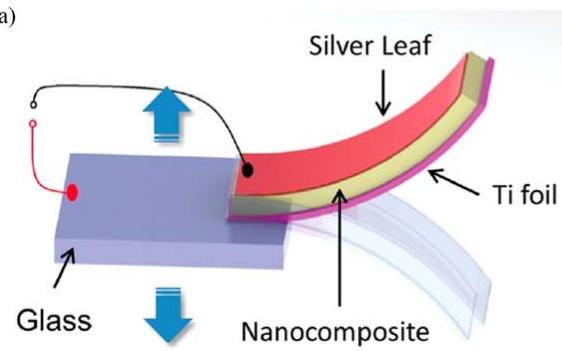
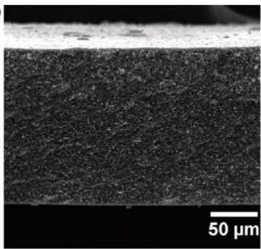
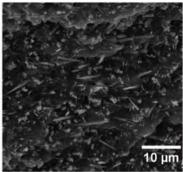
While ZnO nanowires can be designed to achieve good energy harvesting performance, without doping or properly designed electrodes they exhibt high leakage current and limited overall performance. To overcome the limitations posed by the semiconductive propoerties of ZnO nanowires, other piezoelectric materials such as PZT and have been proposed for nanostructured harvesters. One of the initial works on piezoelectric nanocomposites using high aspect ratio fillers was presented by Feenstra and Sodano in 2008 [121] who developed a BaT piezoelectric nanocomposite using electrospun fibers in an epoxy matrix. The BaTiO3 nanowire paint developed in this work was compared experimentally to paint utilizing piezoelectric nanoparticles and, although it possessed a lower sensitivity than PVDF, it was found to provide as high as a three times increase in electromechanical coupling over the previous nanoparticle composite paint. This study was followed up with a theoretical analysis of the nanocomposites with high aspect ratio using micromechanics [122] and validation of the theory [123]. Zhou et al later in 2014 and 2016 demonstrated the process for PZT [124] and lead-free BZT-BCT [125] nanowires with the results showing more than nine times greater energy harvesting output when nanowires were used rather than equiaxial particles. Figure 1 shows an image of a nanocomposite cantilever with randomly oriented nanowires.
Xu et al in 2010 [126] used the hydrothermal growth process developed by Lin et al [127] to grow vertically aligned PZT nanowires. The synthesis approach uses a seeded substrate to grow PZT nanowires via a competitive growth process that results in vertical alignment. Although fabrication of PZT thin films usually requires high temperatures , the hydrothermal process enables the growth of vertically aligned single crystal PZT nanowire arrays at temperatures of only , thus broadening their use by allowing integration with soft materials. Experimental testing of a nanowire array having an active area of 6 mm2 showed the device to be able to generate 0.7 V peak output while having an average power density of 2.8 mW . Additionally, a seven-layer nanogenerator was found to be able to power a commercial laser diode when excited compressively by using a rectifying circuit with storage capacitors. A hydrothermal growth method was employed by Nafari et al in 2017 [128] to produce lead titanate nanogenerators which could function in extreme environments. The study demonstrated that the high Curie temperature of allowed the energy harvester to function without loss of performance at temperatures as high as .
(a
text_image
Silver Leaf Ti foil Glass Nanocomposite
(b)
natural_image
Microscopic cross-section image of a material layer with 50 μm scale bar (no text or symbols beyond scale indicator)
(c)
natural_image
Microscopic view of a granular material surface with 10 μm scale bar (no text or symbols)
Figure 1. (a) Schematic diagram of the BZT–BCT NW/PDMS energy harvester; (b) and (c) cross-sectional SEM images of the 40 wt% BZT–BCT NWs/60 wt% PDMS nanocomposite. Reproduced from [125] with permission of The Royal Society of Chemistry.
(a)
natural_image
Microscopic view of a textured surface with parallel fibrous structures (no text or symbols visible)
(b)
natural_image
Microscopic view of fibrous material structure (no text or symbols visible)
(c)
text_image
σ(t) P V(t)
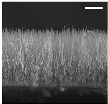
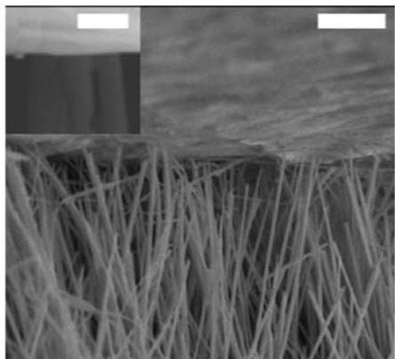
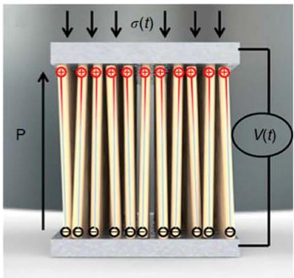
Figure 2. (a) A cross-sectional SEM image of BaTiO3 NW arrays (scale bar, 20 mm), (b) SEM image of the NWs contact with the solder foil by adherence from heating during fabrication process (scale bar, 5 μm) with the inset clearly showing the contact (scale bar, 1 μm), and (c) schematic of piezoelectric voltage generation from NWs. Polarization direction (P) represents the alignment direction of the dipoles. Application of dynamic stress (σ(t)) on NW arrays produces voltage (V(t)) generation. Reprinted by permission from Macmillan Publishers Ltd: [Nature Communications] [129], Copyright 2013.
In an effort to produce more environmentally friendly lead-free nanogenerators, Koka et al in 2013 [129, 130] developed a scalable hydrothermal growth process for vertically aligned arrays of and made comparisons to ZnO nanowires. The nanogenerator was designed using a proof mass mounted to the nanowire array such that the nanowires were compressed when subjected to base excitation, allowing the resonant frequency to be tuned to lower levels (<200 Hz) typically encountered by energy harvesting systems. The nanowire structure and device design are shown in figure 2. The results of testing showed that the nanowires could produce 20 times more energy that the ZnO nanowires although the Schottky barrier was not tuned and no doping was used. Koka and Sodano later in 2014 [131] demonstrated the growth of ultralong nanowires which reduced their stiffness such that a low resonant frequency of 155 Hz could be achieved.
Many of the works performed on nanofiber piezoelectric energy harvesters are summarized in review articles by Chang et al in 2012 [132], Espinosa et al in 2012 [133], and Brisco and Dunn in 2015 [134]. Chang et al [132] reviews several types of piezoelectric nanofiber materials, but focuses on PVDF and PZT nanofiber generators. Espinosa et al [133] focuses on the characterization of nanomaterial properties and the performance of various nanomaterials, while Brisco and Dunn [134] focus their review on nanogenerator devices and material architecture.
2.1.5. Piezoelectret foams. In recent years, researchers have begun investigating the piezoelectric-like response of cellular polymer foam material for use in harvesting vibration energy [135]. The development of piezoelectret foam, also called ferroelectret foam, began in Finland in the 1980s [136]. This class of material is known as an electret; a dielectric material containing permanent electric charge (much like permanent magnets which contain permanent magnetic fields). While these materials are ferroelectret, as opposed to conventional piezoelectric materials which are ferroelectric, they exhibit piezoelectric-like behavior, therefore, are considered appropriate for inclusion in this review. Ferroelectret foam exhibits piezoelectric-like behavior thanks to the permanently charged internal voids of the structure. During fabrication of this material, a polarization process deposits the charge, which then becomes trapped in the voids. The application of mechanical or electrical stimuli causes the charged voids to act as macroscopic diploes, thus yielding piezoelectric-like properties. When compared to conventional piezoelectric polymer materials, piezoelectret foam has the advantage of a large piezoelectric coupling coefficient, up to compared to for PVDF (around seven times greater). Additionally, the cellular structure of ferroelectret foams provides a high level of compliance and low weight.
In 2014, Anton et al [137] investigated vibration energy harvesting using ferroelectret foam material. Their work utilized commercially available foams from Emfit, Corp. and created a pre-tensioned energy harvester with dimensions of . When excited longitudinally (i.e. utilizing the ‘31’ mode) with a peak-to-peak displacement of ±73 μm and at 60 Hz excitation (yielding an acceleration of , the system generated 8 V peak. When configured to charge a 1 mF capacitor, experimental testing showed that the harvester could charge the capacitor to in 30 min while delivering an average power of , an output power comparable to conventional piezoceramic and piezoelectric polymer materials.
Recent studies have also been performed to investigate the use of stacked piezoelectret foam harvesters that employ the mode for improved energy harvesting performance. Pondrom et al in 2014 [138] formed 9- and 10-layer piezoelectret stacks. When harmonically excited in compression, the harvesters generated around of power for a load resistance of 100 MΩ. Later in 2016 [139], this group performed a systematic study to investigate the effect of seismic mass and number of layers on the energy harvesting performance of stacked and folded piezoelectret foams. An eight-layer irradiation cross-linked polypropylene (IXPP) stacked foam exhibited a power of under an acceleration of 1 g, mass of 20 g, and resistive load of 93 MΩ. Ray and Anton in 2015 [140] extended the work of Pondrom et al [138] by increasing the stack layer count to 20 for improved performance. The 20-layer stack was excited harmonically in compression and configured to charge a capacitor. Experimental results showed an output of around 3.8 mW for an optimal load resistance of 650 kΩ. Additionally, the stack was shown to charge a 1 mF capacitor to 1.2 V in 45 min when excited harmonically at resonance (124.4 Hz) with 0.5 g of acceleration. The work performed by Tefft in 2018 [141] expanded upon the study presented by Ray and Anton [140] by developing a more flexible 20-layer foam electret stack with composite graphene electrodes and without any adhesive. The results showed that a 1 mF capacitor could be charged to 1.025 V in 60 min under an acceleration of 0.5 g at resonance (93 Hz).
Another ferroelectret foam material developed by Mohebbi et al in 2017 [142] using nitrogen as the ionizing gas showed a coefficient as high as , which is twice as high as the coefficients reported in the literature for previously fabricated foams using air as the ionizing gas. More recently, Zhang et al [143] in 2018 developed a ferroelectric nanogenerator using parallel tunnel films (laminated structure of fluorinated ethylene propylene (FEP) with large voids in between) with high transverse piezoelectric voltage coefficient of (corresponds to . The relatively high voltage coefficient (due to the small permittivity) of this material compared to PVDF with makes it an ideal candidate for energy harvesting applications. A fabricated lightweight generator with dimensions of showed an output power of under an acceleration of 1 g and a seismic mass of 0.09 g. A thorough review of recent advances in ferroelectret foams and their piezoelectric properties was performed by Mohebbi et al in 2018 [144].
2.2. Piezoelectric transducer types
In order to optimize the energy harvesting efficiency of piezoelectric materials, piezoelectric elements are typically incorporated into transducer devices, which provide a platform for efficient mechanical energy absorption based on the energy source and specific application. Various configurations of piezoelectric transducers proposed in the literature for enhanced energy harvesting performance from different vibration sources are reviewed in this section.
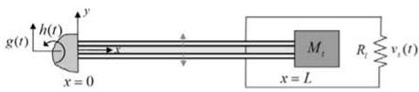
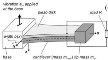
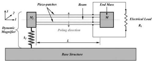
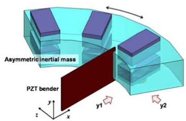
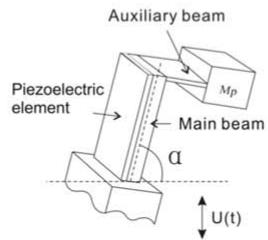
The piezoelectric cantilever beam configuration (active piezoelectric layer glued on a passive substrate beam) is the most utilized piezoelectric transducer in vibration energy harvesting due to its simple structure and convenient fabrication and modeling. The piezoelectric layer is bonded to a passive substrate to increase the strain in the active material. In this configuration, the piezoelectric strain coefficient is usually used to convert mechanical vibration to electrical energy. The most common cantilever beam configurations include unimorph (a single piezoelectric layer bonded to a substrate layer) and bimorph (a single substrate layer with two symmetric piezoelectric layers bonded on each side) devices. The electromechanical behavior of piezoelectric unimorph and bimorph harvesters has been widely discussed in the literature [145, 146]. Piezoelectric beams present a noticeable power generation performance when they are excited at their resonant frequency. Often, an inertial mass is added to the tip of beam harvesters in order to decrease or tune the resonant frequency of the system as well as to improve the mechanical response and output power in low amplitude excitations [147] (figure 3(a)). Various configurations utilized in piezoelectric energy harvesting exist in which the geometries of the active and/or passive materials are altered to give increased performance. Using beams with nonrectangular profiles, such as triangle-shaped beams [148, 149] (figure 3(b)) and trapezoidal cross section beams [150], the energy output and maximum tolerable excitation of the cantilever harvesters can be improved. In addition, altered mechanical boundary conditions and different beam configurations, including designs with a dynamic amplifier support instead of a fixed end [151] (figure 3(c)), an asymmetric tuned mass [152] (figure 3(d)), clamped-clamped boundary conditions with compressive load [150], multiple inertia masses [153, 154], added auxiliary beam [155] (figure 3(e)), cutoff 2 degree-of-freedom beams [156], and multiple beams [157] have been reported by several researchers. Piezoelectric beams are also used as a part of energy harvesting devices for specific applications. Various rotary harvesters [158, 159], acoustic resonator harvesters [160, 161], and piezomagnetic nonlinear harvesters [162, 163] are examples of devices with beam generators. It is important to note that layered piezoelectric transducers (e.g. unimorph and bimorph) tend to degrade in cyclic conditions mostly due to the formation of microcracks in the tensioned layers [164].
(a)
text_image
g(t) h(t) x = 0 y M_t x = L R_t v_s(t)
text_image
vibration a_s applied at the base piezo disk load R width b(x) x y z base cantilever (mass m_bear) tip mass m_ip
(c)
text_image
Dynamic Magnifier Mj Pico-patches Beam End Mass M Electrical Load RL kJ L Poling direction Base Structure
(d)
text_image
Asymmetric inertial mass PZT bender y x y1 y2
(e)
text_image
Auxiliary beam Piezoelectric element MP Main beam α U(t)
(f)
text_image
Piezo Bimorph Micro Probe Micro Ridge Micro Comb Slider
(g)
text_image
Cantilever vibration Input vibration z t Resonating cantilever beam Buckled bridges
text_image
Driving beam Generating beam Front view Tip mass Base
text_image
Inertial Mass Actuation Magnet Mechanical Stopper Frequency Increased Generators (FIG) Spring Suspension Metal Electrodes PZT/Brass/PZT Bimorph
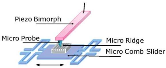
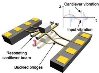
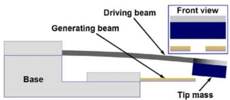
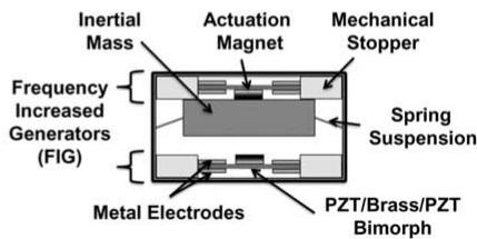
Figure 3. Various piezoelectric beam harvesters with (a) tip mass (reproduced from [147]. © IOP Publishing Ltd. All rights reserved), (b) non-rectangular profile (reproduced from [148]. © IOP Publishing Ltd. All rights reserved), (c) dynamic amplifier support ([151] [2012], reprinted by permission of the publisher (Taylor & Francis Ltd, http://tandfonline.com), (d) asymmetric tip mass (reprinted from [152], Copyright 2013, with permission from Elsevier), (e) added auxiliary beam (reproduced from [155]. © IOP Publishing Ltd. All rights reserved), (f) slider mechanism (© [2007] IEEE. Reprinted, with permission, from [165]), (g) snap-through mechanism (reprinted from [166], with the permission of AIP Publishing), (h) compliant driving beam (reprinted from [167], Copyright 2014, with permission from Elsevier) and (i) impact driven mechanism (© 2012 IEEE. Reprinted, with permission, from [168]).
One issue with cantilever beam energy harvesting is the relatively high resonant frequency and weak energy efficiency of the beams when excited at frequencies below (or above) the natural frequency. Although the addition of an inertial mass can reduce the natural frequency of the beam, large masses lead to an increase in the size and weight of the device as well as mechanical failure. Concerning low frequency applications, different mechanisms of frequency upconversion have been introduced in order to convert low frequency ambient vibration to higher frequency oscillations of the piezoelectric beam generator. Lee et al in 2007 [165] presented a slider mechanism with multiple superelastic shape memory alloy ridges with low frequency movement which excites a piezoelectric bimorph at the natural frequency (figure 3(f)). A similar impact mechanism was employed by Renaud et al in 2009 [169] in a low frequency harvester consisting of a free slider that impacts a pair of piezoelectric bimorphs. A novel design of a frequency upconversion device was proposed by Jung et al in 2010 [166] that consisted of four buckled slender bridges with a proof mass and multiple piezoelectric cantilever beams working based on a snapthrough mechanism (figure 3(g)). Impact driven mechanisms have also been suggested by Gu and Livermore in 2011 [170, 171] and Halim and Park in 2014 [167] that include a compliant driving beam which periodically impacts one or two piezoelectric beams in order to excite the generator beams at their resonant frequency (figure 3(h)). Using a pair of spiral piezoelectric beams, two permanent magnets, and a resonator mass, Galchev et al in 2012 [168] developed another impact driven energy harvester package which is able to produce noticeable power from low frequency vibration (figure 3(i)). Dhakar et al in 2013 [172] suggested a simple frequency upconversion mechanism using a soft spring with a proof mass attached to the tip of a piezoelectric cantilever beam.
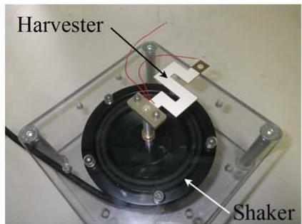
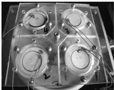
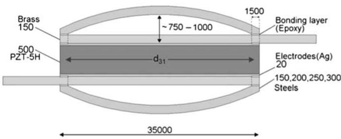
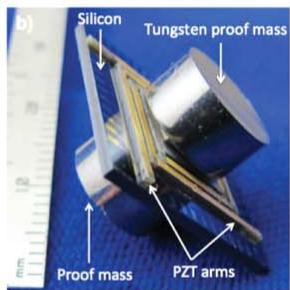
In addition to piezoelectric beam harvesters, researchers have introduced other configurations in order to extend the application of piezoelectric energy harvesters to special practical applications where beam configurations are not applicable or the efficiency is low. Several works suggested using a zigzag-shaped piezoelectric beam with different patterns of beams and proof masses [173–175] (figure 4(a)). The zigzag configuration presents higher power density and lower stress levels, which provides higher durability compared to cantilever beams. Piezoelectric patches with the capability of being attached to the surface of oscillating bodies, such as vehicles and aircrafts, present another form of piezoelectric harvester [32, 176] (figure 4(b)). Pressure energy harvesting from fluids, such as hydraulic pressure or blood pressure, has been suggested with the help of diaphragm-type piezoelectric transducers [177–179] (figure 4(c)). Cymbal-type and bridgetype piezoelectric harvesters have allowed researchers to explore non-resonant and high force amplitude power generation applications [180, 181] (figure 4(d)). Energy harvesting from multi-axis vibration has also been suggested using an S-shaped harvester [182] and a novel three-axis harvester design [183] (figure 4(e)). Using a ring-shaped energy harvester with piezoelectric and magnetic slabs, a contactless high power generator was developed by Xie et al in 2014 [184].
(a)
text_image
Harvester Shaker
text_image
Rectifier +
Capacitor
(c)
natural_image
Four circular electronic components mounted on a transparent base with wires, no visible text or symbols
text_image
Brass 150 ~750 - 1000 1500 Bonding layer (Epoxy) 500 PZT-5H d31 Electrodes(Ag) 20 150,200,250,300 Steels 35000
(e)
natural_image
Close-up of a square electronic component with a circular top and gold pins, placed next to a ruler for scale (no text or symbols visible)
text_image
b) Silicon Tungsten proof mass Proof mass PZT arms
(f)
natural_image
Close-up of a yellow square electronic component mounted on a black curved surface, with wires and a circular hole (no visible text or symbols)
(g)
text_image
PVDF film Polyester film 5 mm
(h)
text_image
Applied impact PU covering PVDF yarn Ag/PA66 yarn Electrodes
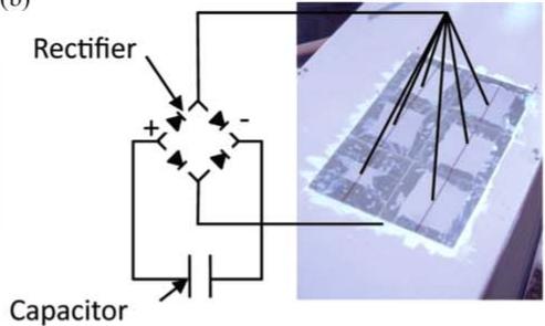
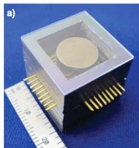
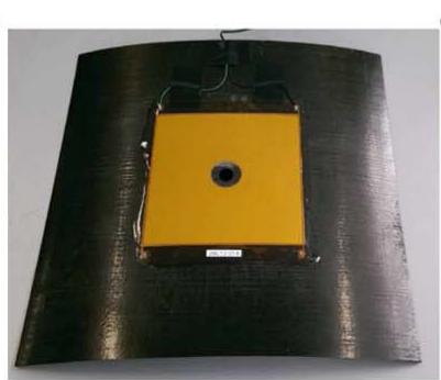
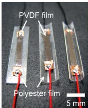
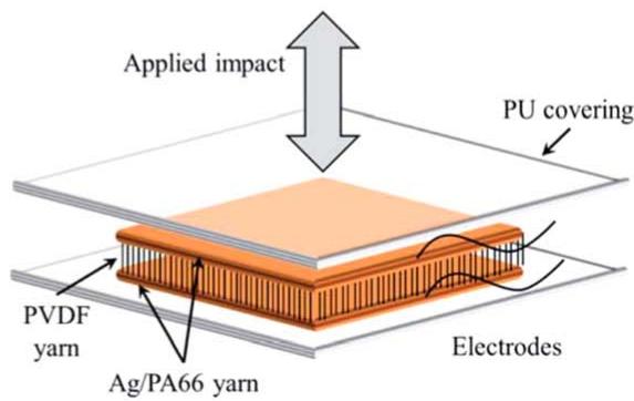
Figure 4. Various piezoelectric transducer configurations including (a) zigzag-shaped beam ([175] (2014) (original copyright notice). With permission of Springer), (b) patch (© 2011 IEEE. Reprinted, with permission, from [32]), (c) diaphragm-type (© 2012 IEEE. Reprinted, with permission, from [179]), (d) cymbal-type (reprinted by permission from Springer Nature: [Springer] [Journal of electroceramics][180] © 2012), (e) three-axis harvester (© 2015 IEEE. Reprinted, with permission, from [183]), (f) plate with MFC patch (reproduced from[185]. CC BY 4.0), (g) pre-curved transducer (reprinted from [186], Copyright 2012, with permission from Elsevier), and (h) fabric-like transducer (adapted from [187] with permission of The Royal Society of Chemistry).
By encapsulating piezoceramic material in Kapton, companies have developed flexible piezoelectric packages with embedded electrodes. Mide Technology (Woburn, MA, United States) has manufactured a soft transducer, called
QuickPack, by encapsulating a conventional monolithic piezoceramic in Kapton. The robustness of the transducer has been greatly improved due to the electrical isolation and the isolation from surrounding environmental effects. In another effort, Smart Material Corp. (Sarasota, FL, United States) has manufactured the Macro Fiber Composite (MCF) which consists of many piezocermic fibers encapsulated in a protective Kapton packaging with an interdigitated electrode configuration. The performance of MFC transducers in energy harvesting was investigated by attaching these elements to different beam and plate components [185] (figure 4(f)). QuickPack transducers have a relatively high power density compared to raw piezoelectric and MFC transducers, while MFC composites exhibit a very large actuation and control authority [188].
Pre-curved substrates have also been utilized to help apply a pre-strain in the piezoelectric layer [186] (figure 4(g)). More recently, piezoelectric fibers were suggested to be used in smart fabric-like textiles in order to develop wearable and super flexible energy harvesters [187] (figure 4(h)). Finally, connecting multiple piezoceramic layers in series, stack configurations can be fabricated. Using the coupling of piezoelectric materials, stack configurations have shown remarkable power conversion efficiency in high force amplitude and non-resonant applications [189–191].
2.2.1. Nonlinear and broadband transducers. One issue correlated with typical piezoelectric energy harvesting systems which have linear resonance mechanisms is that these devices tend to exhibit weak power output when excited at frequencies away from the resonant frequency. This can happen as a result of fabrication imperfections and/or stochastic vibration [22]. Broadband and nonlinear energy harvesting techniques have been introduced and widely investigated during the past decade to improve the energy harvesting performance of linear systems by increasing the response bandwidth of the harvester. The frequency bandwidth of energy harvesting devices can be broadened using passive or active methods. Passive approaches manipulate the dynamics of the system to achieve reasonable response over a range of frequencies. Active approaches utilize an actuation mechanism to change the resonant frequency of the system to match the excitation frequency.
Various mechanical configurations have been utilized in passive broadband systems. Originally, the application of prestressed beams [192, 193] and attractive/repulsive magnetic forces [194] were suggested to adjust the resonant frequency of the harvester. While these passive systems were able to tune the resonant frequency, the frequency bandwidth of the system was not increased. In an attempt to broaden the harvester response bandwidth, Li et al in 2016 [195] presented a bi-resonant structure consisting of two PVDF bimorphs with proof masses and with different resonant frequencies. The cantilevers are placed carefully to ensure impact between the two beams as a result of base excitation at the resonant frequency of one of the beams (figure 5(a)). It was shown that the frequency bandwidth of the system was widened to a range of 14 Hz, which covers the resonant frequency of both of the beams, and the output power was improved by 80% compared to the power output of the two distinct beams.
In active broadband systems, the resonant frequency of the harvester is altered by actuating the structure to match the excitation frequency. One of the original works in this area was presented by Roundy et al in 2005 [150], where a portion of the piezoelectric layers on a cantilever beam was utilized for actuating the structure in order to tune the resonant frequency to match the excitation frequency. However, it was found that the energy consumption of the actuating system was too large to be beneficial. In another work by Lallart et al in 2010 [204], an effective method for increasing the bandwidth of a beam harvester through actively tuning the resonant frequency of the system was suggested. A lowpower control circuit was utilized to actuate the structure according to the displacement and acceleration feedback which resulted in insignificant power draw. More recently, a novel nonlinear approach to enhance the piezoelectric energy harvesting performance of beams and plates was proposed by Zhao et al in 2015 [196, 205] by utilizing acoustic black holes (ABHs) to design a dynamically tailored structure. Attaching piezoelectric elements on the ABHs, high energy density as well as broadband energy harvesting was presented due to a wavenumber sweep mechanism present in high frequency vibration (figure 5(b)).
More effective than passive and active broadband energy harvesting systems, nonlinear energy harvesting has been introduced and widely investigated in recent years. Introducing mechanical nonlinearities to an energy harvester, the frequency bandwidth of the system can be broadened while increasing the response amplitude and power output [206]. The majority of works performed on piezoelectric nonlinear energy harvesting have been based on piezoelectric-magnetic structures. Using multiple pairs of magnets, the resonator can be forced to oscillate around the dynamically stable positions in the system with one potential well (monostable [207–210]) or between multiple stable positions in the system with two, three, or four potential wells (bistable [211–213], tristable [214, 215], and quadstable [216]).
Initial works in this area were performed by Stanton et al [197], Cottone et al [217], and Erturk et al [218] in 2009. In the work of Stanton et al [197], a piezoelectric cantilever beam energy harvester with a tip magnet and two fixed magnets was proposed, which provides one stable position (monostable harvester) (figure 5(c)). Nonlinear oscillation of the cantilever beam around the stable position results in a wider frequency bandwidth and higher power output compared to a similar linear system. Changing the location of the fixed magnets in front of and behind the tip magnet, hardening and softening mechanisms in the beam dynamics are observed, respectively. Another nonlinear energy harvester design was presented by Cottone et al [217] using a bistable piezoelectric inverted pendulum device. The harvester consisted of a vertical piezoelectric bimorph equipped with a tip magnet and a fixed magnet with opposite polarity. Various magnet separation distances were investigated in order to achieve nonlinear oscillation between the two potential wells of the system. The nonlinear design was able to improve the output power of the device up to 600% compared to a similar linear system, while also achieving a wider range of operation frequencies.
A bi-stable Duffing oscillator with two stability positions was presented by Erturk et al [218] in 2009. The device consisted of a piezoelectric harvester beam with a tip magnet and two fixed magnets near the tip of the cantilever. Frequency response results showed that the effective bandwidth of the system was increased compared to a similar linear harvester with significantly improved power output. Another bi-stable system with similar configuration was suggested by Stanton et al in 2010 [198], and different separation distances between the magnets (as a bifurcation parameter) were analytically investigated (figure 5(d)). In 2013, Zhou et al [219] considered magnet rotation in addition to separation distance as another effective parameter on the performance of nonlinear multistable piezoelectric energy harvesters. The system was modeled analytically with the help of a discretization method (Rayleigh-Ritz) and Euler-Bernoulli beam theory. A vertical piezoelectric bimorph cantilever with a tip magnet and two rotatable external magnets was able to provide similar performance as the device reported by Stanton et al [197] in a smaller space. It was shown that the upsweep and downsweep test results are different, and for special magnet angles of 30 to 90 degrees, monostable duffing oscillation occurs within an 18 Hz bandwidth with noticeable superharmonic resonance. Later, in 2015, Jung et al [220] improved the analytical model of the system proposed by Zhou et al [219] by considering the linear terms of the magnetic force. The nonlinear dynamic and magnetic characteristics of the mono-, bi-, and tristable energy harvesters were modeled and discussed in detail. Huguet et al in 2018 [221] showed that by exploiting subharmonics found in bistable systems, the frequency bandwidth of a bistable piezoelectric harvester can be increased by 180%.
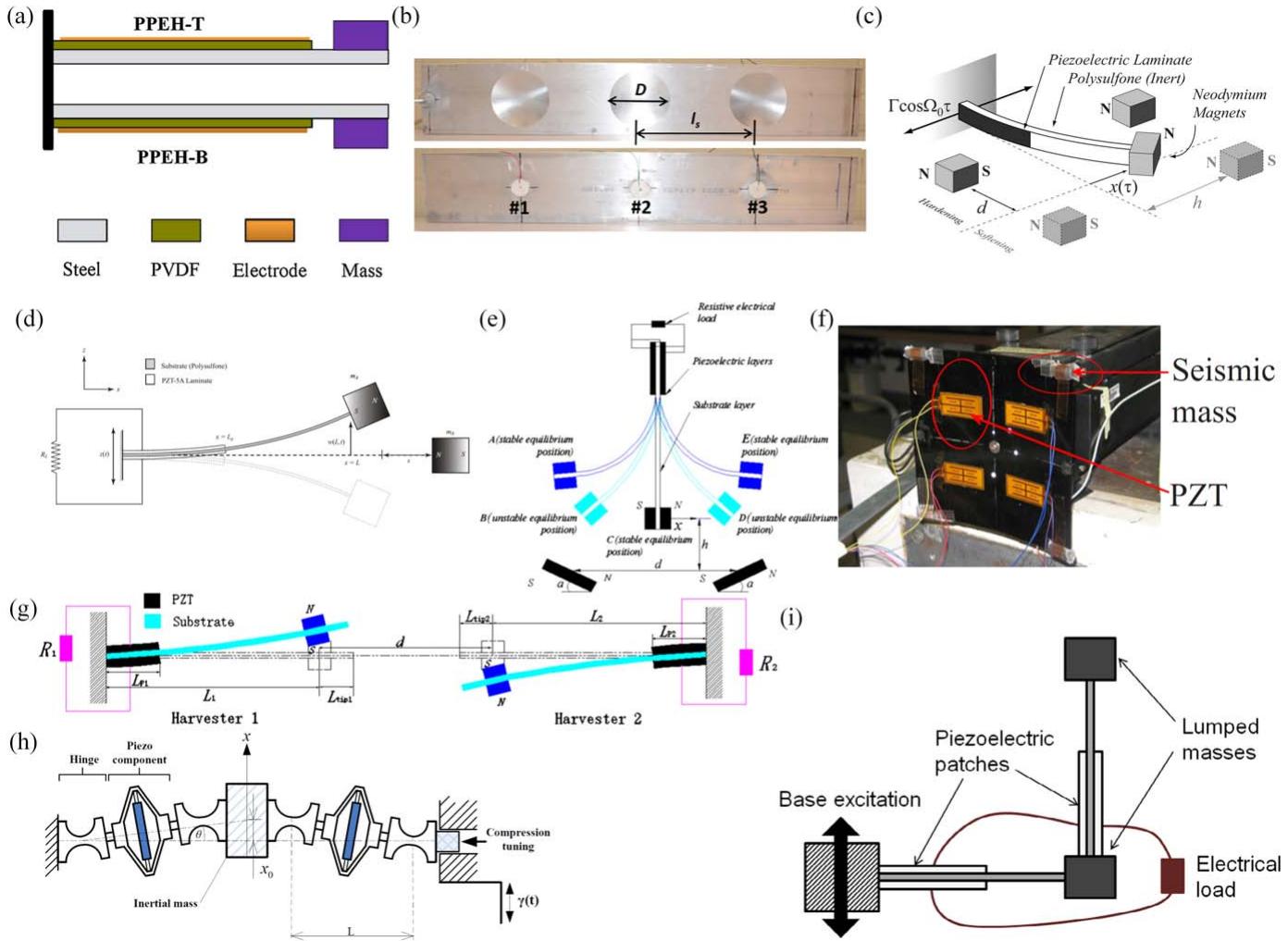
Figure 5. Various broadband and nonlinear piezoelectric harvester designs including (a) two impacting beams (reprinted from [195], Copyright 2016, with permission from Elsevier), (b) harvester on acoustic black hole (reproduced from [196]. © IOP Publishing Ltd. All rights reserved), (c) monostable beam (reprinted from [197], with the permission of AIP Publishing), (d) bistable beam (reprinted from [198], Copyright 2010, with permission from Elsevier), (e) triple-well harvester (reprinted from [199], Copyright (2014), with permission from Elsevier), (f) composite plate (reprinted from [200], with the permission of AIP Publishing), (g) two beams with interacting magnets (reproduced from [201]. © IOP Publishing Ltd. All rights reserved), (h) buckled spring-mass system (reproduced from [202]. © IOP Publishing Ltd. All rights reserved), and (i) L-shaped beams (reprinted by permission from Springer Nature: [Springer] [The European Physical Journal Special Topics] [203] © 2015).
In 2015, Cao et al [222] presented a nonlinear piezoelectric device for energy harvesting from human gait. An analytical model was suggested considering nonlinear time-varying potential functions, as opposed to the constant potential functions used in previous works. The harvester consisted of a piezoelectric bimorph cantilever beam with a tip magnet and two rotatable magnets placed on an external frame. Experiments were performed on the human leg using different harvesters and it was shown that , , and of maximum average output power could be generated using linear, monostable, and bistable harvesters, respectively. More recently, Harris et al in 2017 [223] demonstrated that, with the help of continuous wavelet transformation, phase portraits, and multiscale entropy analysis, a comprehensive platform to characterize the dynamic and electromechanical response of bistable harvesters could be created. The necessity of using a combination of solutions for characterization and optimization of nonlinear multistable harvesters with complex dynamics (such as random and chaotic vibration) was also shown by Wang et al in 2017 [224].
One of the main issues associated with bistable piezomagnetic systems is the relatively high potential well which limits the application of such harvesters to high oscillation amplitude applications to provide sufficient energy to cross the potential well [225]. In 2014, Zhou et al [199] presented a triple-well nonlinear piezoelectric energy harvester consisting of a piezoelectric beam with a tip magnet and two external magnets with a unique arrangement compared to traditional bistable systems (figure 5(e)). Theoretical model predictions and experimental test results over the frequency range between 10 to 35 Hz showed that a significant amount of energy can be harvested over the frequency range of 15.1 to 32.5 Hz under smaller vibration amplitudes compared to traditional bistable systems.
In addition to multistable systems based on cantilever beams and magnets, several researchers have proposed alternative designs of nonlinear energy harvesters. Tehrani and Elliott in 2014 [226] showed that using nonlinear Coulomb damping, a higher level of power can be harvested when the system is excited below the resonant frequency. Arrieta et al in 2010 [200] suggested the application of a bistable piezoelectric composite plate for nonlinear energy harvesting. Experiments under intermittent, limit cycle, and chaotic vibration showed that large power quantities in two distinct broadband frequency ranges can be obtained when the plate oscillates between two stable states (figure 5(f)). The bistable plate has several advantages over bistable cantilever beams, such as a non-magnetic structure which can mitigate the negative effects of magnet use on electronics, a more compact structure due to removing the magnets, and more adjustability because of the two lateral dimensions of the plate. In another study performed by Zhou et al in 2015 [201], a double magnet system consisting of two piezoelectric beam energy harvesters with interacting tip magnets was suggested (figure 5(g)). The system exhibits a multistable nonlinear behavior with a tunable frequency bandwidth through adjustment of the horizontal distance between the endmost magnets. Using a verified analytical model, it was shown that the system exhibits a more complex pattern of magnetic force due to the motion of the two oscillators. The frequency bandwidth of the device was also shown to be dependent on the linear parameters of each harvester without magnetic coupling, such as the horizontal distance between the harvesters and the size and properties of the tip magnets.
An architecture for a wideband piezoelectric energy harvester based on the bistable function of a simple buckled spring-mass system was proposed by Liu et al in 2013 [202]. The harvester consisted of two piezoelectric transducers with a displacement amplification mechanism and a central inertial mass all connected with flexible hinges (figure 5(h)). Analytical modeling and experimentation under chirp and band-limited white noise excitation showed that an output power density of 0.33 mW cm−3 could be harvested, which was significantly higher than the power density of the bistable systems introduced by Mann and Owens [227], Stanton et al [198], Erturk et al [228], Tang et al [229], and Arrieta et al [200].
Leadenham and Erturk in 2015 [230, 231] introduced a modified bistable beam harvester design with the potential of employing piezoelectric and electromagnetic generators. The beam was an M-shaped bent steel spring with 4 piezoelectrics on the roots of the beam and a proof mass in the middle of the beam. The nonconventional beam design was suggested to obviate the relatively high excitation level required to cross the potential wells of magnetic bistable beams and preloaded beams under compression. The system exhibited a nonlinear behavior at very low base excitation of 0.005 g, which was much lower than previous systems, and showed a 660% increase in the bandwidth of vibration at 0.04 g excitation compared to an equivalent linear system.
More recently, application of the internal resonance mechanism for increasing the frequency bandwidth of piezoelectric energy harvesters has been exploited by various researchers. Using an L-shaped beam-mass structure, Cao et al in 2015 [203] achieved a two-to-one internal resonance mechanism for nonlinear energy harvesting (figure 5(i)). It was shown that the frequency bandwidth of the proposed two degree of freedom system was significantly enhanced compared to two equivalent linear systems. An L-shaped beam-mass structure was also utilized by Chen et al in 2016 [232] to explore the feasibility of using the nonlinear modal interaction found in the internal resonance to improve the frequency bandwidth of energy harvesters as well as to study the effect of system parameters on the bandwidth. It was concluded that due to the presence of the peak associated with the two-mode component of the response, the bandwidth of the system increases compared to a linear system. Numerical analysis also showed that the frequency bandwidth is inversely proportional to the external load and piezoelectric electromechanical coupling factor. In a similar work, Liu et al in 2018 [233] also assessed the energy harvesting performance of an L-shaped structure. Experimental results showed that the frequency bandwidth and generated power is highly tunable by changing the length of the piezoelectric beams and the corner mass. A comparison between the investigated nonlinear harvester and a cantilever beam harvester showed that, by optimizing the device geometry, more power could be harvested from the L-shaped beam, while the power density of a cantilever beam is much higher than the L-shaped harvester. Another two-to-one internal resonance mechanism was introduced by Xiong et al in 2017 [234] using a tuned auxiliary resonator added to a primary oscillating structure equipped with a permanent magnet to provide nonlinear forces. Using a validated analytical model, the authors investigated the nonlinear dynamics and energy harvesting performance of the proposed system. Similar works on piezoelectric energy harvesting enhancement using internal resonance phenomenon have been presented by Harne et al in 2016 [235], Wu et al in 2018 [236], and Yang and Towfighian in 2019 [237].
More recently, Sun and Tse in 2018 [238] investigated the linear and nonlinear behavior of a horizontal asymmetric U-shaped piezoelectric energy harvester through finite element analysis, analytical modeling, and a series of experimental tests. The device consists of a primary and an auxiliary piezoelectric unimorph with two proof masses and two fixed permanent magnets. The magnets were deactivated for the linear analysis, while the nonlinear analyses take the magnetic interaction between the magnets and one of the tip masses into account. The results indicated that the nonlinear configuration outperformed the linear device with a maximum generated voltage of 14.18 V under a base excitation of 0.1 g at 15.41 Hz and a load resistor of 10 MΩ. The linear system exhibited 6.7 V of output under a base excitation of 0.1 g at 16.52 Hz. In 2018, Ahn et al [239] introduced a creative way to generate nonlinearity in the vibration response of a cantilever piezoelectric beam with the help of the nonlinear contact mechanism of an oscillating steel ball embedded inside the beam tip mass. Experimental testing was performed on the beam harvester by applying a base excitation with amplitude. The proposed design showed an output power of 1.8 mW at 5 Hz and 13.5 mW at 15 Hz, while the conventional harvester presented an output power of 0.03 mW at 5 Hz and 14.8 mW at 15 Hz. At a fixed power level of (required by a specific wireless sensor), the nonlinear harvester provided a 133% wider frequency bandwidth compared to the linear harvester.
Zhang et al in 2017 [240] investigated nonlinear energy harvesting from a primary structure based on the nonlinear energy sink (NES) principle. The developed device consisted of a base, a primary structure, and an energy harvesting NES. The primary structure is a platform supported by two steel plates and the NES structure is a fixed-fixed beam composed of two bimorphs, a steel beam, and two magnets attached to the beam. Later in 2018, Xiong et al [241] exploited the NES mechanism for simultaneous damping and energy harvesting. A theoretical model of a two degree of freedom system including a primary structure and an added NES structure was provided for analyzing the steady-state response, symmetry breaking and non-periodic responses, and frequency bandwidth with AC and DC electrical interfaces. Numerical simulations showed that 0.8 mW of power could be generated under of base excitation at 12 Hz and with a 200 kΩ load resistor. A maximum frequency bandwidth of 9.44 Hz was reported for a 0.2 mW power threshold.
Lu et al in 2018 [242] introduced a nonlinear piezoelectric energy harvester consisting of three piezoelectric beams equipped with three permanent magnets, which forms an E-shaped energy harvester. Through an analytical model developed based on Hamilton’s principle and a series of experiments, the effects of beam distancing on magnetic interaction, energy conversion efficiency, and jump phenomenon in frequency sweep tests were studied. The half-power bandwidth of the device is improved to 2.67 Hz compared to the 0.8 Hz of the corresponding linear system with a tip mass (i.e. 2.34 times improvement). Research on nonlinear piezoelectric energy harvesting systems has been very attractive and many other configurations of nonlinear harvesters have been investigated by researchers. The reader is referred to the reviews by Harne and Wang in 2013 [20] and
Daqaq et al in 2014 [243] for more examples of research in nonlinear piezoelectric energy harvesting.
2.2.2. Microelectromechanical transducers (MEMS). Lowpower electronics based on very large scale integration (VLSI) circuitry have offered to significantly decrease the power consumption of many electronic components [244]. Progress has enabled chips to consume smaller levels of power, with many systems requiring only tens to hundreds of microwatts. Through decreased power consumption and the development of small-scale microelectronics, the use of microelectromechanical systems (MEMS) vibration-based energy harvesters has become feasible. Piezoelectric MEMS harvesters could enable fully self-powered microelectronics and sensors, and have use in many applications including biomedical devices where size and power usage must be optimized.
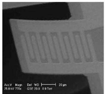
Jeon et al in 2005 [244] presented the first MEMS scale piezoelectric harvester to be fabricated and experimentally characterized. The author’s device consisted of a micro-scale thin-film PZT cantilever harvester, as shown in figure 6(a), and utilized interdigitated electrodes to capitalize upon the higher mode of operation. The cantilever had dimensions of and had a 13.9 kHz resonant frequency. Under resonant excitation with a tip displacement of , the device produced of power at 2.4 V. One of the primary drawbacks to micro harvesters is the high natural frequency which greatly exceeds the frequency of ambient vibration sources. Most mechanical systems exhibit operating frequencies in the range of tens or perhaps hundreds of Hz, therefore, devices with a fundamental resonant frequency in the kHz range are impractical.
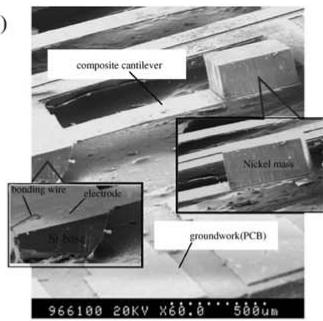
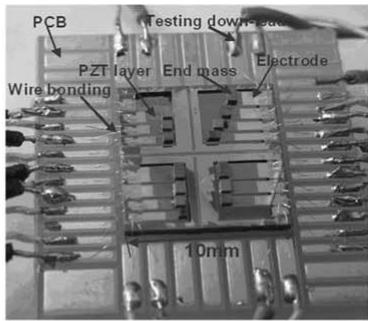
To address the high fundamental resonant frequency of MEMS energy harvesters, Fang et al in 2006 [245] developed a cantilever harvester with very high aspect ratio and a tip mass. The device, shown in figure 6(b), had dimensions of (the substrate thickness was while the piezoceramic thickness was with a nickel tip mass applied, which resulted in a resonant frequency of 609 Hz. The authors found that a voltage output of 0.898 V and power of were generated when excited with 1 g at resonance. The significantly reduced resonance frequency from Jeon et al’s device [244] marked a drastic improvement to the design of MEMS vibration harvesters which operate under practical excitation frequencies. However, the operational frequency is still too high for the majority of mechanical systems. Liu et al in 2008 [246] continued the work of Fang et al with the development of an array of MEMS piezoelectric cantilevers, shown in figure 6(c), that allowed a larger operational bandwidth from 200–400 Hz.
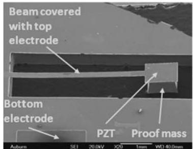
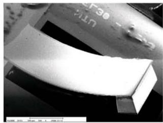
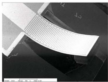
In 2009, Shen et al [247] reduced the resonant frequency of a PZT-based silicon oxide wafer cantilever harvester to below 200 Hz. The cantilever is shown in figure 6(d) and had dimensions of with a 1 μm thick layer of PZT. Experimental testing demonstrated that the harvester had a fundamental frequency of 183.8 Hz and generated under 0.75 g excitation. Lee et al in 2009 [248] compared MEMS energy harvesters functioning under the and piezoelectric modes. Through fabrication of both and PZT cantilevers using an aerosol deposition process, shown in figure 6(e) and (f), respectively, a direct comparison of the two harvester operational modes was performed. The harvester had dimensions of and a proof mass, provided a resonant frequency of , and generated at 2.675 V when excited at 2.5 g, whereas the harvester with interdigitated electrodes and the same dimensions and tip mass had a resonant frequency of 214 Hz, and generated at 2.292 V under 2.0 g excitation. Through these results and further comparisons, the authors found that while the device produced a larger voltage, the device harvests more power.
(a)
natural_image
Microscopic view of a microfluidic structure with periodic grooves (no text or symbols visible)
(b)
text_image
composite cantilever bonding wire electrode hy-based Nickel mass groundwork(PCB) 966100 20KV X60.0 500um
(c)
text_image
PCB Testing down-cath PZT layer End mass Electrode Wire bonding 10mm
(d)
text_image
Beam covered with top electrode Bottom electrode PZT Proof mass Auburn SE1 20.0kV X20 1mm WD 40.0mm
(e)
natural_image
Microscopic view of a curved, layered material sample with no visible text or symbols
(g)
text_image
n … 3 2 1 x’ z D D D
(f)
natural_image
Microscopic view of a curved, ribbed material structure (no text or symbols visible)
(h)
text_image
Accelerometer Tip Mass Shaker Electrode (repaired with silver ink)
text_image
Inlet 2 Inlet 1 Nanofibers Outlet Electrodes
text_image
1000µm voltage multiplier circuit MEMS generator 1200µm
i
text_image
Energy harvester Soldering PCB Wire-bonds 3D printed Part 3mm
(m)
text_image
PCB mount PZT vibrational energy harvester 2 mm
()
natural_image
Green printed circuit board with visible traces and components, no text or symbols present
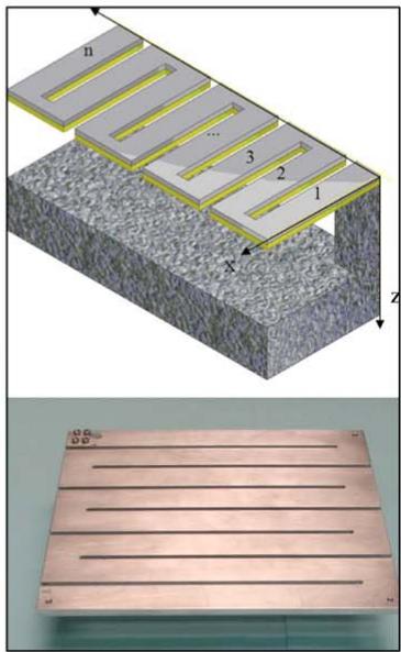
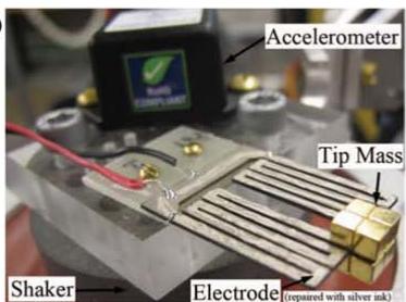
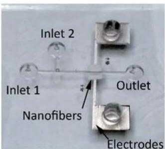
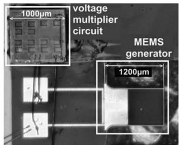
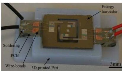
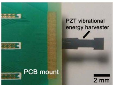
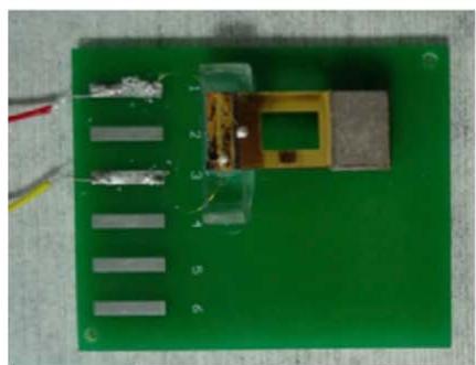
Figure 6. Various piezoelectric MEMS energy harvesting designs including (a) thin-film PZT cantilever (reprinted from [244], Copyright 2005, with permission from Elsevier), (b) high aspect ratio beam (reprinted from [245], Copyright 2006, with permission from Elsevier), (c) cantilever array (reprinted from [246], Copyright 2008, with permission from Elsevier), (d) silicon oxide wafer-based cantilever (reprinted from [247], Copyright 2009, with permission from Elsevier), cantilever (reproduced from [248]. © IOP Publishing Ltd. All rights reserved), (f) cantilever (reproduced from [248]. © IOP Publishing Ltd. All rights reserved), (g) zigzag harvester (reproduced with permission from [249]), (h) zigzag harvester (© 2012 IEEE. Reprinted, with permission, from [250]), (i) harvester with integrated electronics (reprinted from [251], Copyright 2008, with permission from Elsevier), (j) AlN harvester with chip proof mass (reprinted from [252], Copyright 2015, with permission from Elsevier), (k) microfluidic harvester (reprinted from [253]. Copyright 2017 American Chemical Society), (l) harvester with rectangular hole (reprinted from [254], Copyright 2018, with permission from Elsevier), and (m) PZT on metal foil flexible harvester (reprinted from [255], Copyright 2018, with permission from Elsevier).
Karami and Inman in 2011 [249] studied the use of novel geometries as a way to reduce the resonant frequency of MEMS piezoelectric energy harvesters. The authors proposed a zigzag structure, shown in figure 6(g), as a means of increasing the effective length of the beam without increasing the overall device dimension. While the geometry was proposed for MEMS devices, several macro-scale harvesters that contained varying number of elements in the zigzag (figure 6(g) shows an 8 member structure) were tested experimentally. The study’s results demonstrated that 17 times reduction in resonant frequency could be achieved with an 11-member structure compared to a cantilever with the same beam length and thickness.
Berdy et al in 2012 [250] introduced a low frequency piezoelectric MEMS energy harvester with a fixed-fixed design (figure 6(h)) to reduce the torsion in the base of the beams when compared to the zigzag design presented by Karami and Inman [249]. The harvester was tested under an acceleration of 0.2 g at 49.7 Hz and a power of (a power density of was generated. Another MEMS piezoelectric energy harvester was suggested by Yu et al in 2014 [256]. Initially, the device was designed and optimized using finite element simulation considering the resonant frequencies and output voltage of the harvester as the design parameters. A fabricated prototype of the harvester including a PZT cantilever array of five beams and an integrated large silicon proof mass was tested under a vibration excitation of at 234.5 Hz. Using a power conditioning circuit consisting of impedance matching, AC-DC rectifying, instantaneous bleed-off, and voltage regulator circuits, a power output of was achieved.
Integration of piezoelectric materials into MEMS devices has usually been conducted using complicated and expensive material processing techniques such as thin film deposition with laser deposition, sol-gel spin coating, screen printing, direct ink writing, and epitaxial growth [257]. Aktakka et al in 2010 [258] introduced a method to integrate a bulk piezoelectric ceramic, such as PZT and PMN-PT, on silicon substrates with a precise final film thickness of 5 to 100 μm. The method was to bond a bulk piezoelectric material to the silicon substrate and to thin the piezoelectric layer using an enhanced fixed-abrasive lapping/publishing process with a precise uniformity of ±0.5 μm. The advantages of the method include using commercially available piezoelectric materials, a wide range of achievable thicknesses, no polarization requirement after the process, and preserving the material properties of the original piezoelectric material. Energy harvesting test results on a fabricated plate harvester showed that of power can be generated under an acceleration of at 252 Hz, which was remarkably higher than previous works. Tang et al in 2014 [259] developed a MEMS energy harvester that consisted of a PMN-PT thick film and a silicon substrate. The coupling of the piezoelectric was exploited using interdigitated electrodes. The fabrication method previously introduced by Aktakka et al [258] was used in this study to thin a bulk PMN-PT. A fabricated prototype of the MEMS harvester with an active volume of showed an output power of under 1.5 g at 406 Hz. Later in 2017, this group applied a PZT thick film on a berylliumbronzed substrate using the bonding and thinning technology to fabricate a piezoelectric MEMS harvester [260]. The fabricated device with an active volume of exhibited a power output of 0.979 mW under an acceleration of 3.5 g at 77.2 Hz.
The integration of the harvester and power electronics on a single MEMS platform was studied by Marzencki et al in 2008 [251] as a method to further miniaturize the entire harvesting system. A micro-scale cantilever was combined with a miniature voltage multiplier circuit as a single System on a Package (SoP), as shown in figure 6(i). Although, the cantilever beam had a high resonant frequency (1511 Hz), resonant excitation at an amplitude of 0.4 g resulted in approximately 30 nW of regulated power at 3.0 V, and demonstrated an integrated system that could simultaneously harvest and condition energy. Rezaeisaray et al in 2015 [252] designed and fabricated a micro-energy harvester for frequency applications below 100 Hz. The compact design of the harvester includes a silicon substrate covered with aluminum nitride (AlN) piezoelectric material, and the electronic chip employed as a proof mass to reduce the natural frequency of the device (shown in figure 6(j)). The micro-harvester exhibited a power output of 136 nW, an open-circuit voltage of 1 V, and a frequency bandwidth of 10 Hz when subjected to base excitation of at 84.5 Hz and under an external load resistance of 2 MΩ. A validated finite element model of the system showed that by using PZT as the generator element and an SSHI power conditioning circuit, the power output can be increased to 3.1 μW.
Deposition of PZT layers on both sides of a stainless steel substrate using a customized aerosol deposition machine to fabricate an energy harvesting device was suggested by Kuo et al in 2016 [261]. A prototype of the cantilever harvester with dimensions of 9 was tested under a base excitation of 1.5 g at 140.8 Hz and a power output of was measured. Jackson et al in 2017 [262] presented a CMOS compatible silicon-based MEMS cantilever harvester design using aluminum nitride as the piezoelectric layer to be embedded inside a pacemaker capsule with a diameter of 6 mm and length of 40 mm. The harvester showed a power of 60 and 240 bpm, respectively. A micro-scale self-powered viscosity and pressure sensing device was developed by Wang et al in 2017 [253] for an application in microfluidic systems. The device consisted of a layer of PVDF nanofibers deposited on a PDMS substrate to form a microchip (figure 6(k)). The device was tested under a droplet of water representing the droplets or bubbles found in microfluidic systems, and an open-circuit voltage of 1.8 V was collected. Simultaneously, the voltage signal generated by the harvester was analyzed to measure the pressure and viscosity of the microfluid as it passes the microchip.
Tian et al in 2018 [254] presented a low-frequency MEMS piezoelectric energy harvester consisting of a PZT thin film on a flexible phosphor bronze substrate with a proof mass. A rectangular hole was created on the beam harvester to reduce the resonance frequency of the system (shown in figure 6(l)). Exciting the device under a base acceleration of 1.5 g at 34.3 Hz, a power output of (power density of was collected for an optimal matched load resistance of 60 kΩ. In the work by Won et al in 2019 [255], a flexible piezoelectric MEMS beam harvester was developed using PZT thin film with a (LNO) buffer layer deposited on an ultra-thin NiCr-based austenitic steel metal foil substrate (figure 6(m)). The metal foil substrate provides larger compressive stress in the PZT thin film compared to a silicon substrate due to the high thermal expansion coefficient of the foil. Thermal expansion mismatch between the film and substrate is utilized to impose large biaxial stresses and to make a stress-tuned thin film during the fabrication process. A prototype of the harvester beam with the dimension of was fabricated using a simple punching process. Experimental results showed that the device was able to generate a power output of under a 11 kΩ load resistance when subjected to an acceleration of 0.5 g at 127 Hz.
While this section has reviewed several studies in the field of MEMS-based piezoelectric energy harvesters with the goal of reducing their resonant frequency, numerous other studies have been reported in the literature. The reader is referred to the comprehensive reviews of MEMS piezoelectric harvesting presented by Saadon and Sidek in 2011 [21], Priya et al in 2017 [263], and Tian et al in 2018 [264] as well as the book by Kottapalli et al in 2019 [265] for a more complete treatment of the field.
2.2.3. Metamaterials and metastructures. Poor energy conversion efficiency has been a consistent issue with piezoelectric energy harvesting devices due to weak transduction of vibration energy to generator components. Metamaterials and metastructures, with non-traditional physical behaviors, such as negative mass, stiffness, permittivity, permeability, and refraction, have attracted the attention of researchers in recent years to develop new forms of energy harvesting mechanisms with enhanced energy conversion efficiency. Phononic crystals and acoustic metamaterials are the most reported metamaterials for piezoelectric energy harvesting [266]. Phononic crystals are made of periodic distributions of inclusions embedded in a matrix exhibiting absolute acoustic band gaps and negative refraction, which can be used for mechanical filtering as well as to focus traveling elastic waves in specific directions [267]. However, the size of a phononic-based harvester working at low frequencies will be impractically large due to the long acoustic wavelength and sensitivity of performance to the lattice parameters and incident direction. Acoustic metamaterials, on the other hand, utilize independent unit cells with local resonators independent of lattice parameters and direction, which makes them a more practical candidate for energy harvesting [268]. In reviewing the literature, it can be noted that research on acoustic metamaterials for energy harvesting is still in its infancy, and most of the works carried out on developing metamaterials and metastructures are focused on the fundamentals.
One of the initial works on metamaterial energy harvesting was introduced by Gonella et al in 2009 [269], where a honeycomb lattice structure with a microstructure consisting of periodically distributed stiff piezoelectric cantilevers was proposed, and the interplay between phononic bandgaps and piezoelectric microstructure for energy harvesting was discussed (figure 7(a)). In another study by Wu et al in 2009 [270], a PVDF piezoelectric film was placed in the cavity of a sonic crystal (local defect created by removing a rod from a perfect sonic crystal) to convert acoustic energy to electric energy at the resonant frequency of the cavity (figure 7(b)). It was observed from experiments that a PVDF generator placed in the cavity generated 625 times higher voltage than that without the sonic crystal.
In a work performed by Carrara et al in 2012 [271], an elliptical acoustic mirror was suggested in order to enhance structure-borne wave energy harvesting by focusing the propagating waves in a plate. The mirror consisted of several cylindrical stubs mounted on the surface of a plate, which focus the incoming wave energy at a specific point where a piezoelectric energy harvester is placed (figure 7(c)). Using stud spacing that is smaller or on the order of the wavelength of the propagated Lamb wave, the energy harvesting capacity in the frequency range between 25 and 150 kHz was investigated. A maximum power of 126 μW was generated with a 4.5 kΩ load resistance at 50 kHz. The generated power using the acoustic mirror was on average 3075% higher than the system without mirrors for the chosen resistance and frequency ranges. Later in 2013, this group introduced two other concepts of piezoelectric energy harvesters including localization using a 2D lattice structure with an imperfection, and guiding and channeling using an acoustic funnel (figures 7(d) and (e), respectively) [272]. The localization of the energy at the imperfection in the first design was exploited for tuned energy harvesting through matching the defect resonant frequency and excitation frequency. The second design was an acoustic funnel consisting of a periodic arrangement of several stubs on an aluminum plate featuring an open channel along which waves are guided. Using the acoustic funnel, the energy harvesting performance of a piezoelectric disc was increased by 84.5%, thus showing the effectiveness of the concept. The elliptical acoustic mirror introduced by Carrara et al in 2012 [271] utilized bulky
(a)

chemical
Diagram showing piezoelectric cantilevers interacting with a lattice structure, highlighting the defect site.
(b)
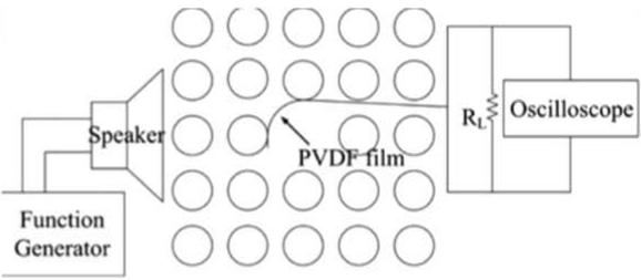
text_image
Function Generator Speaker PVDF film RL Oscilloscope
(c)
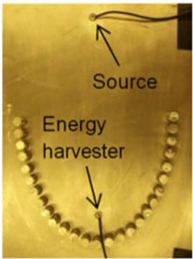
text_image
Source Energy harvester
(d)
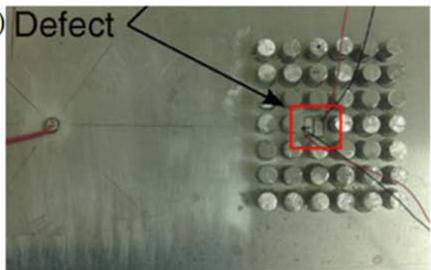
text_image
Defect
(e)
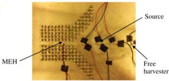
text_image
MEH Source Free harvester
(f)
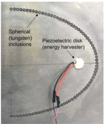
text_image
Spherical (tungsten) inclusions Piezoelectric disk (energy harvester)
(g)
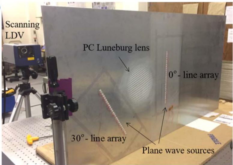
text_image
Scanning LDV PC Luneburg lens 0° - line array 30° - line array Plane wave sources
(h)
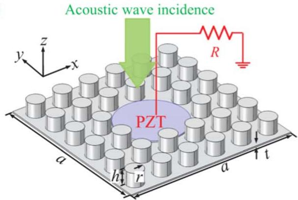
text_image
Acoustic wave incidence PZT R y z x a h r a t
i
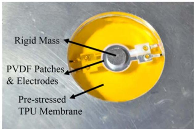
text_image
Rigid Mass PVDF Patches & Electrodes Pre-stressed TPU Membrane
Figure 7. Various metamaterial- and metastructure-based energy harvesters including (a) honeycomb metamaterial structure (reprinted from [269], Copyright 2009, with permission from Elsevier), (b) sonic crystal cavity (reprinted from [270], with the permission of AIP Publishing), (c) parabolic acoustic mirror (reprinted from [271], with the permission of AIP Publishing), (d) lattice with imperfection (reproduced from [272]. © IOP Publishing Ltd. All rights reserved), (e) acoustic funnel (reproduced from [272]. © IOP Publishing Ltd. All rights reserved), (f) elliptical acoustic mirror with embedded spheres (reprinted from [273], with the permission of AIP Publishing), (g) Luneburg lens (reprinted from [274], with the permission of AIP Publishing), (h) planar acoustic metamaterial structure (reprinted from [275], with the permission of AIP Publishing), and (i) membrane-type metamaterial (reproduced from [276]. © IOP Publishing Ltd. CC BY 3.0).
cylindrical attachments, which drastically altered the thin host structure. In 2017, this research group investigated the feasibility of using structurally embedded mirrors using simulation and experimentation [273]. The structure used periodic metallic spheres of tungsten inserted into blind holes in a flat aluminum plate (figure 7(f)). Experimental results showed that the harvester was able to generate 11 times higher power using the embedded acoustic mirror structure as compared to the harvester without the mirror. Another concept studied by this group was omnidirectional elastic wave focusing and energy harvesting using a phononic crystal Luneburg lens [274]. A Luneburg lens was formed by hexagonal unit cells with blind holes of different diameters, which were determined according to the Luneberg lens refractive index distribution obtained by a finite element simulation (figure 7(g)). Two line acoustic wave sources were used to excite the plate and two piezoelectric harvesters were placed at the boundary of the lens. Experimental results demonstrated that the harvesters with the lens could generate 13 times higher power than the harvester without focusing the elastic waves. More recently, Sugino and Erturk in 2018 [277] introduced an analytical modeling framework for an energy harvesting metastructure based on local resonance. The structure was a periodic arrangement of piezoelectric cantilevers with tip masses attached to a primary beam structure. It was analytically shown that useful energy can be harvested from locally resonant metastructures without significantly diminishing their dramatic vibration attenuation in the locally resonant bandgap.
In order to enhance the stub-plate structure with defect proposed by Carrara et al [272], Qi et al in 2016 [275] proposed a concept to scavenge airborne acoustic waves in the direction perpendicular to the plate using a planar acoustic metamaterial structure. The system consisted of an array of silicon rubber stubs periodically deposited on a thin homogenous aluminum plate (figure 7(h)). A defect was created by removing four stubs, and a PZT-5H patch was attached to the defect. Simulation results demonstrated that the device was able to generate 8.8 μW of power when subjected to 2 Pa of acoustic incidence at a frequency of 2.25 kHz. A membrane-type acoustic metamaterial was designed and fabricated by Li et al in 2016 [276] including a pre-stretched thermoplastic circular membrane attached to a center mass and a PVDF patch (figure 7(i)). The membrane was originally designed for sound insulation, and the PVDF generator is placed at the point with maximum strain energy to harvest the sound energy. Experimental results showed that the proposed metamaterial device was not only able to block sound waves with over 20 dB sound transmission loss, but convert the absorbed energy to electric power with an efficiency of 15.3%. In another study by Hu et al in 2017 [278], the performance of a double-mass, acoustic metamaterial unit-cell with a piezoelectric transducer was investigated through analytical modeling. A mass-spring-damper model was initially used to simulate the performance of the unit-cell. The model was then extended to a multicell system, and the effect of various parameters including the piezoelectric coupling coefficient, mass ratio, stiffness ratio, and damping on the vibration suppression and energy harvesting performance was investigated.
2.3. Mathematical modeling of piezoelectric energy harvesters
Mathematical modeling is a useful design tool in the development of optimal harvesting systems. This section presents a brief review of piezoelectric energy harvesting models. Here, the focus will be on models developed to predict the response of the cantilever harvester, which is the most common piezoelectric energy harvesting configuration. Most of the original works on mathematical modeling of piezoelectric energy harvesting utilized simple single degree of freedom lumped parameter modeling approaches [22, 279, 280]. While these models were useful to give insight into the behavior of piezoelectric energy harvesting, their predictions ignored aspects of the electromechanical coupling of piezoelectric systems, and could only predict the first vibration mode [146].
In order to improve the original lumped-parameter models, researchers began to investigated distributed parameter models utilizing the Rayleigh-Ritz discretization, which gives more accurate solutions [279, 281, 282]. Furthermore, researchers have attempted to develop exact analytical solutions of the piezoelectric cantilever harvester based on Euler-Bernoulli beam theory [283–285]. Many of the aforementioned works, however, contain issues leading to inaccuracies; these issues have been summarized by Erturk and Inman in 2008 [286]. Erturk and Inman also presented an accurate analytical distributed parameter model for a unimorph piezoelectric cantilever harvester [145], which has become widely accepted by the energy harvesting community. In 2009, Erturk and Inman also provided exact solutions for symmetric bimorph piezoelectric cantilever energy harvesters [147].
Exact analytical solutions are useful in modeling simple uniform cantilever harvesters, however, many practical piezoelectric harvester configurations are more complicated, and exact solutions cannot be derived. For tapered beam harvesters, thick cantilevers, and asymmetric designs, for example, exact solutions cannot be found. In this case, approximate solutions methods must be employed. Several researchers have presented such approximate solutions, including duToit et al in 2005 [279], who model a symmetric bimorph with a Rayleigh-Ritz type approximation, Elvin and Elvin in 2009 [287], who model a unimorph with an approximate Rayleigh-Ritz formulation, and Erturk and Inman 2010 [288], who present an assumed modes formulation for unimorph, bimorph, and asymmetric cantilever harvesters.
2.4. Energy conditioning circuitry
Piezoelectric energy harvesting systems typically utilize ambient vibrations to excite the harvester harmonically, thereby producing an alternating voltage, or AC power. This AC power must be conditioned before it can be used with any electronics or storage elements requiring DC power. A typical energy harvesting conditioning circuit consists of two main stages: rectification (AC/DC conversion) and regulation (DC/DC conversion). Perhaps the simplest energy harvesting circuit is the full wave rectifier (to convert the AC signal to all positive voltage) combined with a smoothing capacitor (to convert the signal to DC). While simple, the drawbacks to this circuit are that it does not perform any voltage regulation, and it lacks optimization, therefore, it is an inefficient circuit for converting the harvested energy to stored energy. More advanced circuitry containing optimal tuning electronics, sleep modes, wake-up functionality, battery overvoltage protection, and more is often employed in the literature. This section attempts to succinctly summarize work in energy harvesting circuitry without presenting a lengthy comprehensive review.
Most energy harvesting circuits utilize some form of voltage regulation beyond the rectification stage in order to present an appropriate voltage to the load. Various DC-DC converter topologies exist that can be used for this purpose; the selection of which depends on the relative voltage of the harvester output and the desired load input. When the voltage output of the harvester is greater than the voltage requirement of the load, the simplest circuit is a linear voltage regulator. While linear regulators have been employed by various researchers, they are inherently inefficient [289]. Alternatively, a DC-DC switching converter known as a step-down converter or buck converter can be used for an improved solution [290]. In the case where the voltage output of the harvester is less than the voltage requirement of the load, a step-up converter or boost converter can be used. Still yet, there can be cases where the voltage output of the harvester varies in time and may be greater or less than the required load voltage at a given point in time. If this is the case, a buck-boost converter, which combines the functionality of both the buck and the boost converter, may be employed [291].
While switching DC-DC converters can be used to perform the required voltage regulation in an energy harvesting system, their output is still suboptimal. As an improvement to simple switching converters, an important concept was introduced by Lefeuvre et al in 2005 [292] in the form of the synchronous electric charge extraction (SECE) concept. The SECE concept involves synchronization of the energy extracted from the piezoelectric and delivered to the load with the maxima and minima of the harvester’s displacement (which corresponds to generated voltage). In their work, it was shown that this circuit topology provided a four times increase in energy conversion when compared to unsynchronized, direct charging. Following this initial work, the same research group continued to adapt the synchronized harvesting circuit concept. Badel et al [293] and Guyomar et al in 2005 [294] added an inductor to the circuit between the harvester and the rectifier and named the technique synchronized switch harvesting on inductor (SSHI). In 2006, Lefeuvre et al [295] presented the series-SSHI topology that places the switch and the inductor in series with the harvester prior to the rectifier. In their study, both series- and parallel-SSHI topologies are investigated, and results show that up to 15 times increase in energy transfer can be achieved compared to direct charging. Other adaptations to the synchronized switching concept include double synchronized switch harvesting (DSSH) presented by Lallart et al in 2008 [296], enhanced synchronized switch harvesting (ESSH) presented by Shen et al in 2010 [297], synchronized switch harvesting on inductor using magnetic rectifier (SSHI-MR) presented by Garbuio et al in 2009 [298], hybrid-SSHI presented by Lallart et al in 2011 [299], and self-powered synchronized switch harvesting on inductor (SP-SSHI) presented by Liang and
Liao in 2012 [300], among others. Synchronization techniques account for a significant portion of research on circuitry for energy harvesting. A summary of these works has been presented by Chao in 2011 [301].
Another technique employed in energy harvesting circuitry to improve the efficiency of the harvesting process is impedance matching. Maximum energy transfer between a source and a load can be achieved when the impedance of both are matched [302]. Kong et al in 2010 [303] developed an impedance matching circuit that combined a standard diode rectifier with a buck-boost converter operating in discontinuous conduction mode. The duty cycle of the switching buck-boost converter can be tuned to adjust the effective circuit impedance presented to the piezoelectric harvester. The impedance matching technique has also been applied to the buck converter topology by Kim et al in 2007 [304]. Furthermore, the concept of achieving impedance matching using the synchronous charge extraction circuit design previously discussed has been investigated by Lallart et al in 2008 [296] with the introduction of the DSSH technique. The DSSH method combines a series-SSHI front end with a buckboost converter back end. The effective impedance of the harvesting circuit can be tuned by adjusting the capacitor values in the circuit. Results of the study showed that the DSSH technique could provide a five times improvement in efficiency compared to direct charging.
Improving piezoelectric energy harvesting methods and circuits including SECE, SSHI, and impedance matching is an ongoing research field. In order to improve the efficiency of SECE circuits for resonators with strong electromechanical coupling, Badel and Lefeuvre in 2016 [305] briefly described a new technique called frequency-tuning synchronized charge extraction (FTSECE). This technique obviates the two issues correlated with traditional SECE techniques including narrow frequency bandwidth in strongly coupled generators and disability in providing maximum power by controlling voltage drop at the instant of extraction. Later in 2018, Brenes et al [306] applied this method to an experimental setup and observed a noticeable increase in the frequency bandwidth of the harvester when using the FTSECE technique compared to the traditional SECE method. In another work performed by this group in 2018 [307], the bridge rectifier traditionally used in SECE circuits was replaced by a shunt-diode to be used in low amplitude vibration and low piezoelectric voltage (lower than 2V RMS) applications. The method was called unipolar SECE (USECE). Experimental results showed that by combining the high input power of SECE with the high power efficiency of unipolar operation, a power efficiency of 75% was achieved while a traditional SECE circuit provided a power efficiency of lower than 35%. In addition, the USECE circuit exhibited a 200% increase in the power output compared to a SECE power conditioning circuit.
Brenes et al in 2018 [308] introduced the application of the shunt-diode method in piezoelectric energy harvesting along with an impedance matching circuit designed for generators with strong electromechanical coupling. The shuntdiode is directly connected to the piezoelectric transducer to provide a unidirectional voltage signal to be fed to a DC-DC converter designed for power optimization. While SSHI circuits improve the performance of weakly-coupled piezoelectric harvesters, as the electromechanical coupling increases, SSHI becomes less efficient due to relatively constant bandwidth. The shunt-diode architecture was shown to be able to provide larger bandwidth compared to the SSHI in this case. The proposed architecture also exhibited an improved performance for low piezoelectric voltage outputs compared to AC-DC convertors, at which the power efficiency degrades for low voltage levels.
In 2019, Liang et al [309] developed a new method called synchronized triple bias-flip (P-S3BF) to minimize the energy dissipation in passive voltage bias-flip action in the SECE and SSHI circuits. While the bias voltage in passive methods absorbs energy from the piezoelectric to flip the voltage, the bias voltage source injects the backward energy to the piezoelectric element in the active method. Experimental studies on a piezoelectric cantilever showed that the P-S3BF provides 24.5% more power than an SSHI circuit and 287.6% more power than a standard bridge rectifier circuit.
While this section provides a brief summary of some of the notable work in piezoelectric circuits, numerous other works have been reported in this area over the past decade. The reader is referred to the review articles by Guyomar and Lallart in 2011 [310] and Szarka et al in 2012 [311] as well as the book chapters by Badel and Lefeuvre in 2016 [305], and Chen in 2019 [312] for a more comprehensive review on piezoelectric energy harvesting conditioning circuits.
3. Piezoelectric energy harvesting devices and applications
While the previous section focused on advancements to piezoelectric materials, harvester configurations, mathematical modeling, and energy harvesting circuitry, the remainder of this review focuses on recent work in the development of energy harvesting devices and applications presented in the literature. The main sources of vibratory energy investigated for piezoelectric harvesting in the last decade include fluid sources, human body motion, animal activity, vibration of infrastructure, and vehicle motion. Various piezoelectric energy harvesting devices introduced in the literature from these sources are discussed in this section. Additionally, works on multifunctional energy harvesting, multi-source energy harvesting, and harvesting in other applications not covered in the previous categories are also discussed.
3.1. Energy harvesting from fluids
Kinetic energy of fluid flow found in various environments presents opportunities for piezoelectric energy harvesting. Particularly, there are environments rich in fluid flow but lacking in structural vibration where harvesting flow energy can lead to autonomous power sources for electronic devices. Flowing media offers relatively high density kinetic energy which is usually readily available. Piezoelectric transduction can be utilized to convert the energy available in flow of both water (liquids) and air to useable electrical energy. Energy conversion from fluid flow kinetic energy to electrical energy is reported in the literature using various configurations such as windmills, cantilevers, films, plates, flags, membranes, and piezo discs [313]. The following subsections are organized by device type.
3.1.1. Harvesting airflow using windmill-style harvesters. Harvesting of wind energy is typically investigated using windmill-style harvesters and flutter-style harvesters. Energy harvesting from wind power has been far more attractive than many other sources because of wide availability and its perpetual nature, providing continuous mechanical energy [314]. One limitation in wind energy harvesting is the relatively low speed of wind near the ground due to boundary layer effects and physical obstructions such as trees and structures [315].
The original work on piezoelectric energy harvesting using a windmill-style device was presented by Priya et al in 2005 [316, 317] (shown in figure 8(a)). Following the work of Priya et al [316, 317], an optimized windmill harvester with a much simpler design was proposed by Myers et al in 2007 [318] (figure 8(b)). Since 2007, several researchers have tried to improve the design of windmill harvesters in order to reduce harvester dimensions and cut-in speed, and to increase power efficiency. A windmill harvester design was suggested by Tien and Goo in 2010 [319] consisting of a single PZT composite cantilever. A conventional fan with exciter teeth installed on the hub of the turbine was utilized to excite the harvester, as shown in figure 8(c). A prototype harvester equipped with a bimorph with dimensions of was tested in a wind tunnel and a maximum power of 8.5 mW at 26 V was obtained, however, the corresponding wind speed was not described. A novel windmill harvester design using impactinduced resonance of piezoelectric beams was presented by Yang et al in 2014 [314]. The device, shown in figure 8(d), consists of a rotating fan in a polygon arrangement, three steel balls placed inside the polygon, and 12 piezoelectric bimorphs. The piezoelectric harvesters are struck with the steel balls when wind rotates the windmill and, consequently, the bimorphs oscillate at their natural frequency. A small-scale windmill with an overall diameter of 31 mm generated a peak power of with an optimum load resistor of 20 kΩ at a rotational speed of 200 RPM (note, the wind speed was not reported).
Considering the relatively low available energy level in small-scale windmill generators, several researchers have suggested different designs of contact-less windmill energy harvesters to minimize the effects of friction on power generation. In 2011, Bressers et al [320] introduced a contact-less wind turbine utilizing a nonlinear piezomagnetic configuration. The harvester consists of a vertical axis Savonius wind turbine rotor with permanent magnets and multiple piezoelectric bimorphs with tip magnets (figure 8(e)). Their optimization study resulted in a windmill with 2 blades and 4 magnets along with 6 piezoelectric beams and with overall dimension of , which generated 1.2 mW of power at 9 mph (4 m s−1 ) wind
(a)
natural_image
Close-up of a white propeller with four blades, displayed against a background of printed materials (no visible text or symbols)
(b)
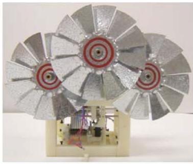
natural_image
3D rendering of a mechanical fan assembly with metallic blades and red circular targets, mounted on a beige base (no text or symbols visible)
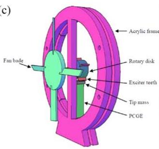
text_image
c) Fan bade Acrylic frame Rotary disk Exciter teeth Tip mass PCGE
natural_image
Close-up of a metallic fan or propeller device with visible blades and mounting base, displayed against a blue background (no text or symbols)
(d)
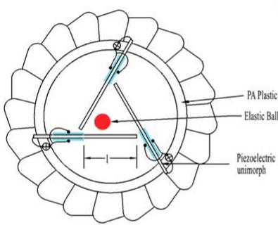
text_image
PA Plastic Elastic Ball Piezoelectric unimorph
natural_image
Circular petri dish with needle-like structures and a central white object, no visible text or symbols
(e)
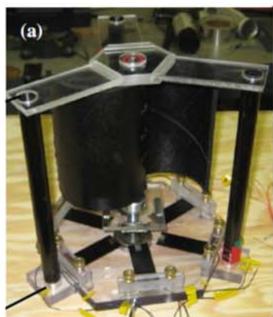
natural_image
Mechanical experimental setup with a black cylindrical component mounted on a metal frame, surrounded by wiring and components (no visible text or symbols)
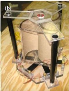
natural_image
Mechanical device with transparent frame and black legs, no visible text or symbols
(f)
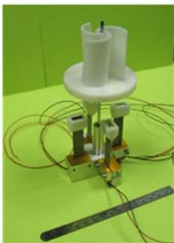
natural_image
Laboratory setup with white cylindrical components and connected tubing on a green surface (no visible text or symbols)
(g)
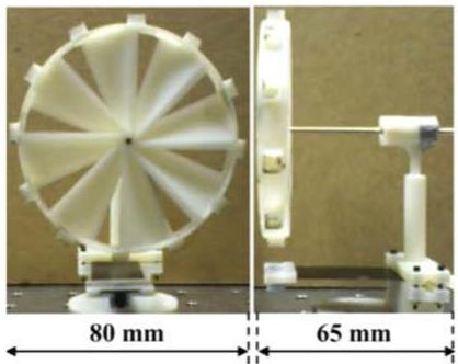
natural_image
Two views of a white plastic turbine or fan device with labeled dimensions (80 mm and 65 mm), no other text or symbols visible.
(h)
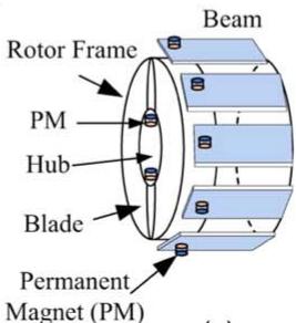
text_image
Rotor Frame PM Hub Blade Permanent Magnet (PM) Beam
(a)
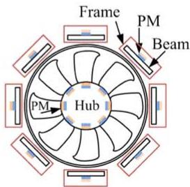
text_image
Frame PM Beam PM Hub
Figure 8. Various windmill-style piezoelectric energy harvesters including (a) Priya’s harvester (reproduced from [317]. © IOP Publishing Ltd. All rights reserved), (b) Myers’s harvester (reprinted from [318], with the permission of AIP Publishing), (c) windmill with exciter teeth (reproduced with permission from [319]. © Emerald Publishing Limited all rights reserved), (d) impact induced harvester (reprinted from [314], with the permission of AIP Publishing), (e) contact-less piezomagnetic harvester ([320] (2011) (© Springer Science & Businees Media, LLC 2011). With permission of Springer), (f) contact-less piezomagnetic windmill (reprinted from [321], Copyright 2013, with permission from Elsevier), (g) flat profile fan ([315] [2014], reprinted by permission of the publisher, Taylor & Francis Ltd, http:// tandfonline.com.), and (h) contact-less multi-magnet windmill (© 2015 IEEE. Reprinted, with permission, from [322]).
speed. A similar design of a windmill utilizing a contact-less mechanism was developed by Karami et al in 2013 [321]. Four vertical PZT bimorphs with dimensions of 0.38 mm3 were mounted on the base of a miniature Savonius vertical axis wind turbine. A permanent magnet was attached to the tip of each beam and five magnets were placed in the lower disc of the turbine blades such that when rotated, the magnetic interaction excites the cantilevers. Two versions of the piezoelectric windmill were tested in a wind tunnel and it was found that for the optimal design, as shown in figure 8(f), a power of 4 mW could be generated by a single bimorph at a wind speed of 10 mph (4.47 m s−1 ). A startup speed as low as was reported for the contact-less windmill. Another windmill-style piezoelectric energy harvester design was proposed by Zhang et al in 2017 [323] in which a rotating fan blade is attached to a turntable that strikes several piezoelectric beams. Wind tunnel tests showed that the device generated 2.57 mW of power at 14 m s−1 wind speed and with a 10 MΩ load resistor.
A problem with the windmill designs proposed in this section is that they work at relatively high wind speeds (around 10 mph or , where even conventional electric generators operate efficiently. In order to reduce the cut-in speed, Kishore et al in 2014 [315] introduced a new wind turbine harvester design. The design is different from conventional wind turbines in many ways; the rotor has 8 fantype blades with a flat-type profile, blade solidity of 50 %, and it employed a single piezoelectric bimorph generator (see figure 8(g)). Conventional turbines usually have 2–3 tapered blades with airfoil profiles, solidity of 5–7%, and employ electrical generators. The 72 mm diameter horizontal axis wind turbine rotor included 12 equally spaced permanent magnets attached around its periphery and a piezoelectric bimorph with a tip magnet clamped near the base of the turbine. In order to reduce the startup speed, the piezoelectric beam is used as an actuator for start the energy harvesting process at wind speed. Once started, the device switches to energy harvesting mode and generates of power at the wind speed of . The initial actuation period consumes 7.2 s worth of harvested energy by the fan at this speed. The wind turbine was successfully used to charge a motion detector sensor. In another work, Rezaei-Hosseinabadi et al in 2015 [322] improved the power efficiency of contact-less wind turbines with a new arrangement of magnets and piezoelectric beams, as shown in figure 8(h). The 31 mm diameter turbine generated a maximum power of and could operate at a cut-in speed as low as . In order to enhance the power harvesting efficiency of wind energy harvesters, Biccario et al in 2017 [324] suggested a new architecture of harvesting circuit that employs two storage capacitors: a small and fast-to-charge capacitor to power the active start-up circuit, and a large capacitor for storing the power. It was shown that voltage signals as low as 0.05 V can be harvested with only 200 ms start-up time with no amplitude limitation afterwards.
Table 1 summarizes the transducer type, generator material, dimensions, wind speed, cut-in speed, and output power of the different windmill-style piezoelectric harvesters described herein. This table attempts to provide the most relevant information for comparison purposes; additional details of each study can be found within the respective manuscripts.
3.1.2. Harvesting of airflow using flutter-style harvesters.
Various flutter-style piezoelectric wind harvesting systems, as the second most reported configuration for energy harvesting from fluid flow, have been developed in the literature including fluttering beams with attached airfoils, wake galloping (a fluttering beam in the wake of a fixed bluff body), and fluttering beams with attached bluff bodies (galloping body). Using flutter-style harvesters, some issues associated with windmill-style harvesters, such as complexity, high fabrication and maintenance cost, and unfavorable scalability at small-scale due to high viscous drag and friction, can be alleviated [325].
In an initial investigation into flutter-style wind harvesting with an attached airfoil, Tan and Panda in 2007 [326] subjected a piezoelectric beam mounted at an angle to transverse airflow. In order to achieve improved coupling between airflow and the beam, a compliant plastic flapper was installed on the free end of the cantilever. A prototype of the harvester with overall dimensions of showed a power output of around 155 μW when subjected to an optimal wind speed of . Similar designs of wind harvesters based on the stalk-leaf architecture were proposed by Li and Lipson in 2009 [327] and optimized in 2011 [328] (figure 9(a)). A plastic flapper was attached to the flexible PVDF stalk in parallel-flow stalk and cross-flow stalk configurations. Experimental test results showed that the cross-flow design could provide significantly more power than the parallel-flow design. A double layered PVDF crossflow long stalk with dimensions of mm3 harvested power when subjected to wind speed. The power density of this device was 17 times higher than the device presented by Tan and Panda [326]. Bryant and Garcia in 2011 [329, 330] expanded upon the work presented by Tan and Panda [326] by developing an aeroelastic flutter energy harvester containing a rigid flap connected to a piezoelectric cantilever harvester through a ball bearing revolute joint (figure 9(b)). When subject to airflow, oscillation of the flap causes flutter of the system. The beam had a length of 25.4 cm and width of 2.54 cm, while the flap had a width (span) of 13.6 cm and a length (semichord) of 2.97 cm. Two PZT harvesters with dimensions of were placed on opposite sides at the beam’s root. Experimental testing in a wind tunnel showed that the harvester could provide 2.2 mW of power at a wind speed of , with a cut-in speed of . Stamatellou and Kalfas in 2018 [331] also studied the energy harvesting performance of a PVDF cantilever with a plastic extension subjected to swirling airflow. The transducer generated of power when placed in a swirling flow at and with a load resistor of 150 Ω.
In addition to flutter-style harvesters with attached airfoils, researchers have also investigated wake gallopingbased flutter harvesters. Akaydin et al in 2010 [332] investigated the energy harvesting performance of a PVDF bimorph located in the wake of a cylinder at high Reynolds numbers subjected to turbulent flow (figure 9(c)). The threeway interactions of flow, electromechanical piezoelectric behavior, and electronics were numerically modeled using a multiphysics finite element model, and experimental validation was performed. The piezoelectric harvester had dimensions of and was able to generate of power when subjected to wind speed. It is necessary to note that due to weak conversion of flow energy to mechanical vibration energy, the total efficiency of the device was very low. Experimental test results obtained from laminar airflow (provided by a fan) and turbulent airflow (provided by a wind tunnel) showed that 35 μW of power at turbulent wind speed could be harvested, which is sufficient to power a commercial thermometer. Later in 2012 [336], this group presented a self-excited fluidic energy harvester consisting of a cylinder attached to the tip of a piezoelectric cantilever. Wind tunnel experiments showed that the device generated 0.1 mW of power at a wind speed of . In another study by Zhang and Wang in 2016 [337], a harvester consisting of a rigid cylinder attached to two piezoelectric bimorphs was placed against fluid flow to harvest energy from vortex induced vibrations and wake induced vibrations of an additional large cylinder. It was shown that the wake induced vibrations of the large cylinder led to more than 400 times higher power than a harvester with only vortex induced vibration (without additional cylinder). More recently, Ravi and Zilian in 2019 [338] developed a three-dimensional multiphysics finite element model for flow driven piezoelectric energy harvesting that involves the threeway interaction of fluid flow, piezoelectric material, and the controlling electrical circuit. A system of integral equations describing incompressible Newtonian flow, electromechanical behavior of a piezoelectric patch on an elastic substrate with equipotential electrodes, and the attached circuit was derived and solved using space-time finite element discretization with static condensation of the auxiliary fields and Galerkin’s method. Usman et al in 2018 [339] presented a novel piezoelectric energy harvesting configuration based on wake galloping using a unimorph piezoelectric beam. Two cylinders with circular cross-sections of similar diameter are considered in the design while the upstream cylinder is fixed and the downstream cylinder is placed on top of a piezoelectric cantilever consisting of an MFC film. The lift component of force was considered the main cause of vibration. Test results showed that the system provides good performance for wind speeds higher than , and an optimum spacing distance equal to three times the diameter of the cylinders was achieved. Using an MFC beam with dimensions of , a peak voltage of 27 mV was achieved under a wind speed of .
Table 1 . Summary of various windmill-style piezoelectric energy harvesters .
| Author | Device | Transducer Type | Generator Material | Dimensions | Wind Speed (m s-1) | Cut-in Speed (m s-1) | Output Power |
| Priya et al [317] | Fan-type windmill | Piezoelectric bimorph | PZT-5H | 114 mm diameter × 60 mm width, 60 × 20 × 0.6 mm3 each beam | 4.47 | — | 7.5 mW |
| Myers et al [318] | Vane-type vertical windmill | Piezoelectric bimorph | PZT-5H | 96 × 107 × 66 mm3 generator, 178 mm vane diameter | 4.47 | — | 5 mW |
| Tien and Goo [319] | Fan-type windmill | Piezo-composite beam | PZT-5H | 72 × 12 × 0.5 mm3 beam | Not specified (less than 5 m s-1) | — | 8.5 mW |
| Yang et al [314] | Fan-type windmill using impact-induced resonance | Piezoelectric unimorph | PZT ceramic | 31 mm diameter | Not specified (200 RPM rotation speed of the fan) | — | 613 μW |
| Bressers et al [320] | Contact-less windmill, Savonius turbine | Piezomagnetic generator | — | 165 × 165 × 229 mm3 | 4.02 | — | 1.2 mW |
| Karami et al [321] | Contact-less windmill, Savonius turbine | Piezomagnetic generator | PZT-5A | 80 × 80 × 175 mm3 | 4.47 | 2 | 4 mW |
| Zhang et al [323] | Fan-type windmill | Piezoelectric cantilever | PVDF | 41.5 × 16.3 × 0.22 mm3 | 14 | — | 2.57 mW |
| Kishore et al [315] | Fan-type windmill | Piezomagnetic generator | — | 80 × 100 × 65 mm3 | 1.8 | 1.8 | 450 μW |
| Rezaei-Hosseinabadi et al [322] | Fan-type windmill | Piezomagnetic generator | PZT-5A | 31 mm diameter | 0.9 | 0.9 | 363 μW |
(a)
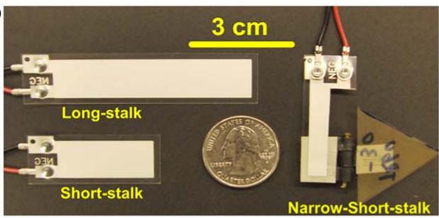
text_image
3 cm Long-stalk Short-stalk Narrow-Short-stalk
(b)
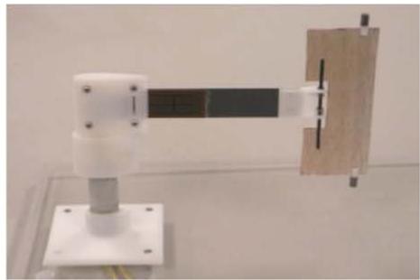
natural_image
Mechanical assembly with white and gray components mounted on a base, next to a wooden block (no visible text or symbols)
(c)
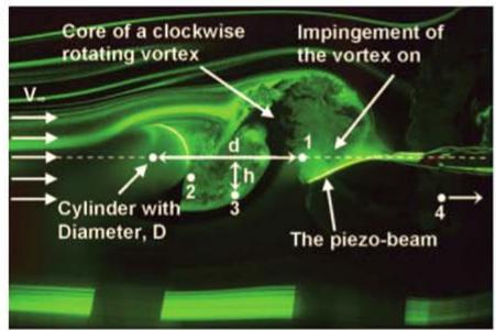
text_image
Core of a clockwise rotating vortex Impingement of the vortex on V. Cylinder with Diameter, D d h 1 2 3 4 The piezo-beam
(d)
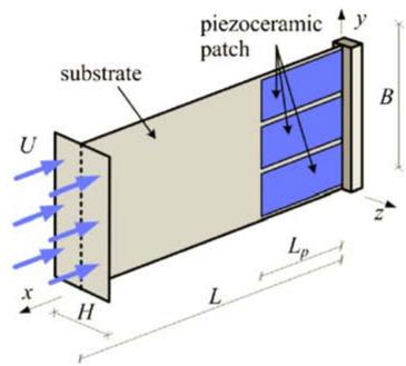
text_image
substrate piezoceramic patch U x H L y B z Lp
(e)
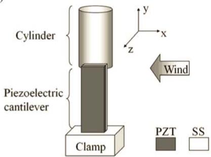
text_image
Cylinder Piezoelectric cantilever Clamp y x z Wind PZT SS
(f)
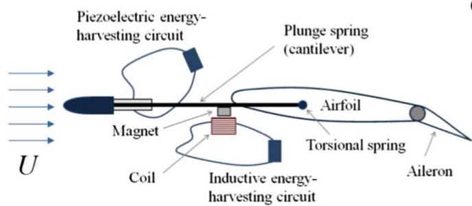
text_image
Piezoelectric energy-harvesting circuit Plunge spring (cantilever) Airfoil Magnet Coil Inductive energy-harvesting circuit Torsional spring Aileron U
(g)
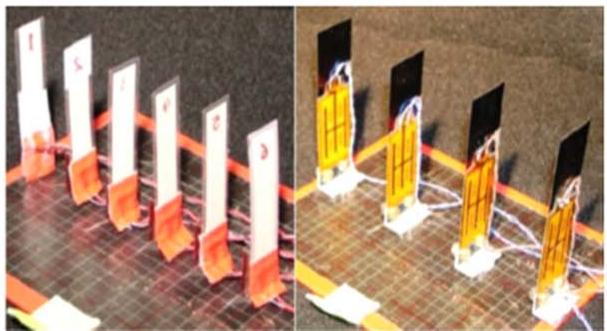
natural_image
Two technical diagrams showing vertical supports mounted on a grid surface, with no visible text or symbols.
Figure 9. Various flutter-style harvesters including (a) flutter stalk (reprinted from [328], with the permission of AIP Publishing), (b) flap with revolute joint (reproduced from [330]. © IOP Publishing Ltd. All rights reserved), (c) wake harvester (reproduced with permission from [332] by SAGE Publications, Ltd), (d) T-shaped harvester (reprinted from [333], with the permission of AIP Publishing), (e) beam with cylindrical extension (© 2013 IEEE. Reprinted, with permission, from [325]), (f) airfoil-based hybrid harvester (reproduced with permission from [334]. Copyright © 2014 by the American Institute of Aeronautics and Astronautics, Inc. All rights reserved), and (g) piezoelectric grass (reproduced from [335]. © IOP Publishing Ltd. All rights reserved).
A final method of flutter-based energy harvesting involves attaching a bluff body to a piezoelectric beam. Kwon in 2010 [333] developed a galloping body using a T-shaped cantilever beam that facilitates aeroelastic flutter under wind excitation (figure 9(d)). The occurrence of vortex shedding was observed around the T-shaped end of the device when placed in airflow causing flutter in the beam. A T-shaped harvester with overall dimensions of , and six MFC transducers each) attached to the root of the beam, was placed inside a wind tunnel. Experimental results showed that the device could generate a maximum power output of 4.0 mw at a cut-in speed corresponding to flutter of 4 m s−1. Another flow energy harvester design consisting of a cross-flow PZT cantilever beam with a cylindrical extension was presented by Gao et al in 2013 [325] (figure 9(e)). The piezoelectric beam was equipped with a layer and the cylinder was a lightweight 36 mm long hollow cylinder. As a result of turbulence created around and in the wake of the cylinder, the piezoelectric beam could vibrate in the direction normal to the flow, and it was shown that 0.035 mW of average power could be generated at a wind speed of 5 m s−1 . Similar results were found by Amini et al in 2017 [340] for a comparable piezoelectric device.
The concept of piezoelectric energy harvesting under combined base excitation and vortex induced vibration (galloping in the beam with attached bluff body) was proposed by Dai et al in 2014 [341]. The harvester was a multilayer piezoelectric cantilever beam with a cylindrical tip mass similar to the design proposed by Akaydin et al [336]. A nonlinear distributed parameter model of the generator was developed and the results were compared to the experimental results of Akaydin et al [336] for the case of energy harvesting from beam galloping for the sake of verification. Considering the combined vibration sources, it was observed that the behavior of the system changed from periodic to period-n and quasi-periodic due to the co-presence of base excitation frequency and shedding frequency, and the output power of the system was significantly higher than the output power of the two separate vibration sources. A piezoelectric beam with dimensions of generated a power output of 1.6 mW under a wind speed of 1.2 m s−1 and base excitation of 0.05 g. In similar works, Yan et al in 2014 [342] and Bibo et al in 2015 [343] presented and verified analytical models for a piezoelectric bimorph cantilever beam with a tip mass (bluff body) under combined galloping and base excitation. For wind speeds below the galloping speed, a periodic response corresponding to the base excitation frequency with a corresponding high amplification in power generation was observed, while, for speeds higher than the galloping speed, two peak frequencies were observed in the response of the system.
Erturk et al in 2010 first introduced the concept of piezoaeroelastic systems (those that couple piezoelectricity and aeroelasticity) [344]. In this research, piezoelectric coupling was introduced to the plunge degree of freedom of a typical wing, and the developed linear lumped-parameter model was experimentally validated. Experiments showed that an electrical power of 10.7 mW could be generated at a linear flutter speed of and a 100 kΩ load resistance. In addition, the effect of piezoelectric power generation on the linear flutter speed and generated nonlinearities in the system were discussed. Later in 2011 [345], this group enhanced the aeroelastic energy harvesting of a similar system by introducing combined piezoelectricaeroelastic nonlinearities to the system. Piezoelectric devices were installed on the support beams of the airfoil in the plunge degree of freedom. Initially, the linear response of the device near the flutter speed was evaluated. Then, power output was improved by adding nonlinearities to the pitch degree of freedom leading to chaotic oscillations and twice as much harvested energy. Wind tunnel testing showed that the harvester could generate 27 mW of power at a wind speed of . Although the system tested was quite large and impractical, it demonstrated the benefits of nonlinearity in piezoaeroelastic energy harvesting. Later in 2013 [346], the same group proposed another airfoil-based harvester design that utilized piezoelectric transduction and electromagnetic induction for power generation. A 2D model with focus on linear system parameters was proposed to investigate various parameters including radius of gyration, chordwise offset of elastic axis from the centroid, frequency ratio, load resistance, and internal coil resistance. Adding a control surface to the airfoil and introducing a 3D model in 2014 [334], they showed that the power output of the system was improved. In addition, the 3D model offered broader design space and parameters to reduce the cut-in speed and to maximize the power output of the harvester (figure 9(f)).
The concept of piezoelectric grass, an array of vertical piezoelectric cantilever beams to harvest energy from turbulence induced vibration (figure 9(g)), was introduced by Hobeck and Inman in 2012 [335]. This concept involves arrays of robust piezoelectric beams designed for energy harvesting from low-velocity, turbulent flows. PZT cantilevers and PVDF cantilevers were employed to fabricate two prototypes of the presented concept. Wind tunnel testing demonstrated that a power of 1.0 mW could be generated by each beam (with substrate dimensions of and piezoelectric dimensions 0.1524 mm3 ) at a wind speed of 11.5 m s−1 .
More recently, in 2017, Silva and De Marqui [347] presented the concept of self-powered active control of base excitation and aeroeleastic oscillation of wings using a sensor-actuator piezoelectric system. A plate-like wing with two piezoelectric layers attached to the root of the wing on the top and bottom surfaces was analytically, numerically, and experimentally investigated. The top piezoelectric element was employed as an actuator and the bottom one was utilized as a sensor and energy harvester. Results showed that the device was able to fully damp the flutter vibration of the wing for a certain level of oscillation amplitudes. For small amplitude vibration, the system could not harvest enough energy to power the actuator, but the oscillation of the wing was damped to some extent due to the presence of the passive piezoelectric patches. In another study, the application of piezoelectric laminated plates in energy harvesting from yawed flow was suggested by Tang and Dowell in 2018 [348], and a computational model of the piezoelectricaeroelastic coupled system was developed. Orrego et al in 2017 [349] proposed a flexible piezoelectric membrane placed in an inverted flag orientation where the trailing edge of the flag is fixed and the leading edge is free to move [350]. A flag with five 60 mm long piezoelectric beams generated a peak power of 1–5 mW cm−3 for wind speeds between 5 and 9 m s−1 .
Table 2 summarizes the transducer type, generator material, dimensions, wind speed, cut-in speed, and output power of the different flutter-style piezoelectric harvesters described herein. This table attempts to provide the most relevant information for comparison purposes; additional details of each study can be found within the respective manuscripts.
3.1.3. Energy harvesting from liquid flow. Research on energy harvesting from liquid flow has been more limited compared to energy harvesting from airflow due to the availability of the source. On the other hand, liquid flow sources, in particular water, can provide continuous energy accompanied with a higher energy density compared to airflow. Given the rich kinetic energy content of water flow along with a small dependence on environmental conditions, there is promising potential for energy harvesting from water sources.
Table 2. Summary of various flutter-style piezoelectric energy harvesters .
| Author | Device | Transducer Type | Generator Material | Dimensions | Wind Speed (m s-1) | Cut-in Speed (m s-1) | Output Power |
| Tan and Panda [326] | Flutter beam with plastic flapper | Bimorph | — | $76.7 \times 12.7 \times 2.2 \text{ mm}^3$ | 6.7 | 3 | 0.155 mW Peak |
| Li et al [328] | Stalk-leaf harvester | Bimorph | PVDF | $72 \times 16 \times 0.41 \text{ mm}^3$ | 8 | 4 | 0.61 mW peak |
| Bryant et al [329] | Rigid flap with revolute joint | Bimorph | PZT | $283.7 \times 136 \times 0.9 \text{ mm}^3$ | 7.9 | 2.6 | 2.2 mW peak |
| Stamatellou and Kalfas [331] | Piezoelectric film with plastic extension | Rectangular film | PVDF | $22 \times 13 \times 0.2 \text{ mm}^3$ | 2 | — | 3 μW |
| Akaydin et al [332] | Cantilever in the wake of a cylinder | Bimorph | PVDF | $30 \times 16 \times 0.2 \text{ mm}^3$ | 7.23 | — | 0.004 mW |
| Akaydin et al [336] | Cantilever with cylindrical tip mass | Bimorph | PZT-5A | $267 \times 32.5 \times 0.9 \text{ mm}^3$ beam | 1.192 | — | 0.1 mW |
| Usman et al [339] | Two cylinders wake galloping | Unimorph | MFC film | $85 \times 30 \times 0.3 \text{ mm}^3$ beam | 7 | 4 | 27 mV across MFC |
| Kwon [333] | T-shaped flutter | Bimorph | PZT | $100 \times 60 \times 30 \text{ mm}^3$ | 4 | 4 | 4 mW peak |
| Gao et al [325] | Cantilever with cylindrical extension | Bimorph | PZT | 67 mm total length | 5 | 2 | 0.035 mW |
| Dai et al [341] | Cantilever with cylindrical tip mass (combined vortex-induced and base excitation) | Bimorph | PZT | $267 \times 32.5 \times 0.635 \text{ mm}^3$ beam | 1.2 | — | 1.6 mW under 0.05 g base excitatoin |
| Sousa et al [345] | Airfoil with piezoelectric supports in plunge degree of freedom | Bimorph | QP10N QuickPack | 500 mm long beam | 10 | — | 27 mW |
| Hobeck and Inman [335] | Piezoelectric grass | Bimorph | PZT | Four $101.6 \times 25.4 \times 0.406 \text{ mm}^3$ beams | 11.5 | — | 4 mW |
| Orrego et al [349] | Inverted flag | Piezoelectric membrane | PVDF | $60 \times 120 \times 0.2 \text{ mm}^3$ | 9 | — | 5 mW |
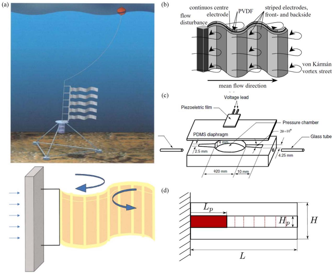
Figure 10. Various piezoelectric devices for liquid flow energy harvesting including (a) energy harvesting eel (© 2001 IEEE. Reprinted, with permission, from [351]) (b) fluttering flag (© 2004 IEEE. Reprinted, with permission, from [352]), (c) liquid flow pressure fluctuation harvester (reproduced from [354]. © IOP Publishing Ltd. All rights reserved), and (d) sectioned piezoelectric fluttering flag (reprinted from [355], Copyright 2015, with permission from Elsevier).
Taylor et al in 2001 [351] introduced one of the earliest works on harvesting liquid flow using piezoelectric materials. They presented an energy harvesting eel consisting of a PVDF bimorph emerged in water flow (figure 10(a)). A prototype eel with dimensions of 24 cm × 7.6 cm × 150 μm was fabricated and tested in a flow tank. A peak voltage of around 3.0 V was measured at a water velocity of . In another work performed by Pobering and Schwesinger in 2004 [352], two types of hydropower piezoelectric harvesters including a PZT bimorph, and a PVDF fluttering flag, were proposed (figure 10(b)). Simulation results showed that the
PVDF flag harvests up to 32 W m of power, while a PZT bimorph with dimensions of could generate around 7 μW of power. In 2009, this group performed a comprehensive analytical, numerical, and experimental study on the power generation using a short piezoelectric cantilever beam subjected to liquid and gas flow [353]. Using a bluff body attached to the beam, a Von Karman vortex street (turbulence) was created in order to achieve a pressure differential on the beam surfaces and to apply upward and downward forces periodically. The system was analyzed analytically to investigate oscillation in the first resonant mode of the beam and to avoid neutralization of charge. The system was comparatively tested in wind and water channels, and a higher efficiency was observed when the system was subjected to water flow due to the higher energy density of water compared to air. For a geometrically non-optimized system, 0.8 V and 0.1 mW of power output was generated in the water channel for a flow speed of 45 m s−1 .
In the study performed by Wang and Ko in 2010 [354], this group investigated the ability of a PVDF film to harvest energy from the fluctuations of pressure created by a pump in a fluid system. The harvester consists of an in-line flow channel, a flexible diaphragm, and a PVDF film with dimensions of mm3 (PVDF thickness of 28 μm, the remainder is a polymer coating) attached to the diaphragm (figure 10(c)). The diaphragm transfers the pressure ripples of the liquid flow to the piezoelectric film. Placing the flow-based harvester in a pressure line with oscillations of 1.196 kPa at 26 Hz, of power was experimentally obtained. Following this work, Wang and Liu in 2011 [356] proposed a similar design of the harvester with a PZT film as the generator component. Experimental results showed that using a PZT film with dimensions of , a power output of 0.45 nW could be generated for a fluctuation pressure of 20.8 kPa at 45 Hz.
In a more recent study conducted in 2015, Pineirua et al [355] investigated the effect of piezoelectric electrode arrangement along a fluttering flag through a series of analytical and experimental studies (figure 10(d)). The verified analytical model showed that the number and position of piezoelectric elements have a critical role in energy harvesting performance. It was shown that a larger number of piezoelectric segments can improve the efficiency of the fluttering harvester, in particular, for systems with higher fluid to solid inertial ratio (mass ratio) where the modal structure responds to shorter wavelengths and shorter electrodes can capture the flag deformation.
Table 3 summarizes the transducer type, generator material, dimensions, flow characteristic, and output power of the different fluid flow-style piezoelectric harvesters described herein. This table attempts to provide the most relevant information for comparison purposes; additional details of each study can be found within the respective manuscripts.
3.1.4. Energy harvesting from other fluid sources. While the availability and relatively high kinetic energy content of air and water flow has attracted the attention of researchers to these sources, higher energy densities can be found in some other fluid sources including ocean wave and hydraulic systems. Ocean waves, with higher energy density of about compared to 0.1–0.5 kW of wind near the surface (4–30 times higher energy density), have a promising potential for energy harvesting [357]. High pressure hydraulic lines with pressure ripples induced by pumps are another fluid source for energy harvesting reported in the literature.
One of the first works on energy harvesting from ocean waves was presented by Zurkinden et al in 2007 [358]. A PVDF cantilever beam with dimension of 1.25 mm3 was modeled on the sea bed and subjected to ocean waves through analytical and numerical analysis. A piezoelectric-buoy harvester design was introduced by Murray and Rastegar in 2009 [359] based on a two-stage electric generator concept (figure 11(a)). Three designs of the harvester including heaving-based, pendulum design pitching, and four-bar linkage pitching harvesters were presented. The output of a 76 mm diameter, and 914 mm long heavingbased harvester was 60–180 mW.
In 2014, Xie et al [360, 361] proposed two designs of piezoelectric energy harvesters to generate power from transverse and longitudinal wave motion. The former harvester was a horizontal piezoelectric cantilever beam attached to a square column on a fixed support under a floating structure (figure 11(b)) and the later device was a piezoelectric cantilever column equipped with a tip proof mass (figure 11(c)). Analytical modeling results showed that using an optimized design of both devices, an RMS power of 30 W could be generated from the horizontal device with cantilever dimension, and 55 W could be generated by the vertical harvester with 3 m cantilever length. Another piezoelectric-buoy energy harvester was proposed by the same research group in 2015 [362] for power harvesting from deep and intermediate ocean waves with relatively higher available power than sea bed and shallow waters. The buoy consisted of a slender floater attached to a larger cylindrical sinker to compensate the vertical oscillation of the buoy body (figure 11(d)). Several PZT beams were attached horizontally to the floater close to the ocean surface in order to generate electricity from the relative motion between the ocean wave and the buoy. Using a novel analytical model, the length and width of the floater, the diameter of the sinker, and the ratio of wave length to the length of the cantilever were optimized. The device with 1 m long and 0.2 m wide piezoelectric beams was able to generate 24 W of power from ocean waves. More recently, in 2017, the concept of energy harvesting from ocean waves using multistable mechanisms was introduced by Younesian and Alam [364], and the stability characteristics of a simple buoy-generator-restoring spring system were well discussed.
In addition to oceans and streams, the application of energy harvesting from rain drops has been suggested by several researchers [365–369]. In the work proposed by Ilyas and Swingler in 2015 [363], a PVDF-based energy harvester was presented. They utilized a commercial sensor as the active piezoelectric film under the impact of rain drops (figure 11(e)). Different stages of drop impact were discussed, modeled, and experimentally investigated, and results showed 2.5 nW of power generation from a single harvester with dimension of mm3 and a load resistance of 2.2 MΩ for a single impact. Later, in 2017, they developed a multipiezoelectric generator to enhance the energy conversion efficiency of the harvester [370]. The device is a unimorph with 3 separate impact regions covered by PVDF patches and with overall dimension of and connected in parallel to a 1 MΩ load resistor. Optimizing the surface angle, surface condition, and impact region, the efficiency of the device was improved to 0.671%. A review of energy harvesting from rain drops has been published by Wong et al in 2015 [371], and different harvester designs including piezoelectric bridge, solid film, and cantilevers were compared. It was found that the most efficient configuration for rain energy harvesting is a PVDF bridge. Outdoor environmental conditions (sunlight, wind, water, etc), application with large and typical raindrops, and non-continuous energy were listed as the main challenges of energy harvesting from raindrops.
Table 3. Summary of various piezoelectric devices for energy harvesting from liquid flow.
| Author | Device | Transducer Type | Generator Material | Dimensions | Flow Characteristic | Output Power |
| Taylor et al [351] | Energy harvesting eel | Bimorph | PVDF | $240 \times 76 \times 0.150 \text{ mm}^{3}$ | $0.5 \text{ m s}^{-1} \text{ flow}$ | 3 V |
| Pobering et al [353] | Fluttering flag | Bimorph | PZT | $14 \times 11.8 \times 10.35 \text{ mm}^{3}$ | $45 \text{ m s}^{-1} \text{ flow}$ | 0.1 mW |
| Wang and Ko [354] | Fluid fluctuation harvester with PVDF | Diaphragm | PVDF | $25 \times 13 \times 0.150 \text{ mm}^{3}$ | 1.196 kPa pressure fluctuation at 26 Hz | 0.2 μW |
| Wang and Liu [356] | Fluid fluctuation harvester with PZT | Diaphragm | PZT | $8 \times 3 \times 0.200 \text{ mm}^{3}$ | 20.8 kPa pressure fluctuation at 45 Hz | 0.45 nW |
(a)
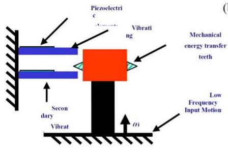
text_image
Piezoelectric Vibrating Mechanical energy transfer teeth Second dary Vibrat Low Frequency Input Motion
b
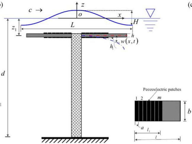
text_image
c → z o x H z₁ L h w(x,t) h₁ d Peozoelectric patches 1 2 m b a l₁ l
c)
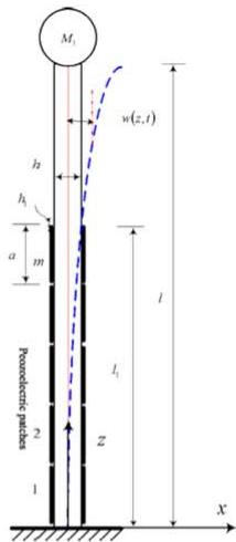
text_image
M₁ h h₁ a m l w(z,t) l₁ z 1 2 Poonoelectric plaites X
(d)
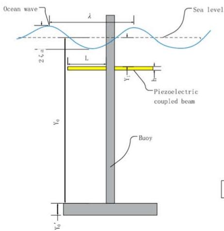
text_image
Ocean wave λ Sea level 2ζ₀ L Piezoelectric coupled beam Y₀ Buoy Y₀’
(e)
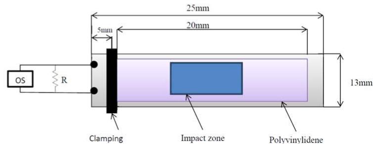
text_image
OS R 25mm 20mm 5mm 13mm Clamping Impact zone Polyvinylidene
Figure 11. Various piezoelectric devices for energy harvesting from sea and rain including (a) piezoelectric-buoy harvester (reproduced with permission from [359]), (b) transverse wave harvester (reprinted from [360], Copyright 2014, with permission from Elsevier), (c) longitudinal wave harvester (reprinted from [361], Copyright 2014, with permission from Elsevier), (d) deep ocean wave harvester (reprinted from [362], Copyright 2015, with permission from Elsevier), and (e) rain harvester (reprinted from [363], Copyright 2015, with permission from Elsevier).
In the work of Cunefare et al in 2013 [372], a hydraulic pressure energy harvester for electricity generation from the pressure ripple in closed hydraulic systems with a piezoelectric stack was presented. The high power intensity of hydraulic systems provides a suitable ground for piezoelectric energy harvesting. The energy harvester included a piezoelectric stack within a housing connected to the hydraulic line with an interface separating the fluid from the harvester. Two prototypes were fabricated for exploring the electromechanical performance and interface effects. The stack was a soft PZT with dimensions of . The interface was a 0.0762 mm thick aluminum diaphragm. The hydraulic system was a nine-piston pump operating at 1500 RPM with a fundamental ripple frequency of 225 Hz. The test results showed an output power of 1.2 mW from a dynamic pressure ripple of 400 kPa and with a 120 Ω resistor. The experiments also showed that the power efficiency was improved using area ratios more than unity at the interface. The output voltage was also calculated via an analytical model and compared to the test results successfully. The study showed promising potential of off-resonance energy harvesting from hydraulic systems. Zhou et al in 2018 [373] introduced a novel piezoelectric tubular energy harvester configuration in order to generate power from fluctuating fluid pressure inside tubes. The proposed system consists of a PZT tube with inner radius of 8 mm, outer radius of 10 mm, and length of 20 mm subjected to 0.2 MPa internal fluctuating pressure at 10 kHz attached to a resistive load of 2.62 kΩ. An analytical model of the device was developed and an exact solution was derived. Simulation results showed that 0.1 W of power could be generated using the proposed device.
Table 4 summarizes the energy source, transducer type, generator material, dimensions, input excitation, and output power of the different alternative fluid-based piezoelectric harvesters described herein. This table attempts to provide the most relevant information for comparison purposes; additional details of each study can be found within the respective manuscripts.
3.2. Energy harvesting from the human body
The human body presents a unique area where piezoelectric energy harvesting can be exploited. Kinetic energy from limb motion, strain energy from muscle forces, and thermal energy are the main sources of harvestable energy that can be found in the human body. One of the first surveys on the possibility of energy harvesting from the human body to power wearable devices was presented by Starner in 1996 [374]. Body heat, walking, and upper limb motion were found to produce significant energy, while walking was shown to be the most practical energy source. Breathing, finger motion, and blood pressure, on the other hand, were found to present lower energy levels (less than 1.0 W). Similar findings have been reported by other researchers on the energy available for harnessing from the human body [375, 376].
Table 4. Summary of various piezoelectric devices for energy harvesting from alternative fluid energy.
| Author | Device | Energy Source | Transducer Type | Generator Material | Dimensions | Input Excitation | Output Power |
| Murray and Rastegar [359] | Piezoelectric-buoy harvester | Ocean waves | Two-stage buoy mechanism | PVDF | $76.2 \times 76.2 \times 914.4 \text{ mm}^3$ | 0.05–11.5 m wave height | 60–180 mW |
| Xie et al [360] | Transverse wave harvester | Transverse ocean waves | Horizontal bimorph | PZT-4 | 2 cantilevers of $2.4 \times 1 \times 0.01 \text{ m}^3$ | 4 m wave height | 30 W RMS |
| Xie et al [361] | Longitudinal wave harvester | Longitudinal ocean waves | Vertical bimorph | PZT-4 | $3 \times 1 \times 0.05 \text{ m}^3$ | 3 m wave height | 55 W RMS |
| Wu et al [362] | Deep ocean wave harvester | Transverse ocean waves | Bimorph-buoy | PZT-4 | 2 cantilevers of $1 \times 0.2 \times 0.006 \text{ m}^3$ | 3 m wave height | 24 W RMS |
| Ilyas and Swin-gler [363] | Rain harvester | Rain drops | Unimorph | PVDF | $25 \times 13 \times 3 \text{ mm}^3$ | Single drop | 2.5 nW |
| Cunefare et al [372] | Hydraulic harvester | Hydraulic pressure | Stack | PZT | $6.8 \times 6.8 \times 30 \text{ mm}^3$ | 400 kPa pressure ripple | 1.2 mW |
| Zhou et al [373] | Tubular energy harvester | Pressure inside tubes | Tube | PZT-5A | 8 mm inner radius, 2 mm thickness, 20 mm length | 0.2 MPa fluctuating pressure | 0.1 W |
The development of novel energy harvesting methods and materials, along with advances in low-power electronic technologies used in portable devices, have made piezoelectric energy harvesting a potential solution to obviate the dependency of wearable electronics on batteries. Similarly, implantable active medical devices, such as cardiac pacemakers, cardioverter defibrillators, cardiac monitors, and neurological brain stimulators, can benefit from piezoelectric energy harvesting technology. By implementing energy harvesting technologies in implantable devices, subsequent maintenance operations and corresponding costs and risks can be highly reduced. In general, the studies performed on piezoelectric energy harvesting from human body sources can be categorized into two main areas: wearable harvesters and implantable devices.
3.2.1. Wearable devices. The ubiquitous presence of low power portable electronic devices and the lifespan limitations of batteries have encouraged the research community to develop wearable energy harvesting devices with the ability to generate micro- to milliwatts of energy. This amount of energy can be sufficient to power small electronics such as heart rate monitors and respiratory rate monitors, or, possibly, mobile phones.
One of the early works on wearable energy harvesting devices was presented by Paradiso’s research group at MIT Media Laboratories in 1998 [377, 378], in which piezoelectrics were integrated into shoes. Similarly, in 2010, Rocha et al [379] presented a shoe harvester design consisting of PVDF polymers and an electrostatic harvester integrated into the sole of a shoe. Due to the relatively high available energy of human gait, other researchers have tried to improve the energy harvesting efficiency from shoes using different harvester designs. In the work performed by Xie and Cai in 2014 [380], an amplification mechanism including several piezoelectric bimorphs and sliders was proposed, and 0.41 mW was experimentally obtained, which showed higher harvested power than previous works (figure 12(a)). In order to increase the power output of wearable harvesters in low frequencies, Jung et al in 2015 [381] suggested a flexible energy harvester with curved piezoelectrics located in the shoe insole. The curved generator was also utilized in a watch strap. Simulation results showed that 3.9 mW of power was available from the curved generator, while, the shoe experiment showed 25 V and 20 of electrical output for normal walking of a 68 kg person. Zhao and You in 2015 [382] suggested two shoe harvester designs to enhance power efficiency and comfortability (figure 12(b)). The harvesters consist of multilayer PVDF films embedded inside a plastic host and a flexible silicon rubber host, and sandwiched between two wavy surfaces. Test results showed that a higher power of 1 mW was generated by the harvester with plastic host, while the design with silicon host showed to be more comfortable. More recently, Ma et al in 2017 [383] introduced an interesting application of an insole-based piezoelectric energy harvesting device for unobtrusive user identification/verification. The idea is based on the uniqueness of gait pattern of each individual, which can be reflected in the output voltage signal of the energy harvester [384]. Experiments on 20 individuals showed an accuracy of identification of around 96% in addition to of stored power in a storage unit.
Work presented by Granstrom et al in 2007 [392] investigated the use of piezoelectric energy harvesting from the cyclic loading of the straps of a backpack. The work sought to developed a backpack with the capacity to generate power during walking as a means to reduce the amount of batteries carried by soldiers, emergency personnel, field workers, etc. Energy harvesting straps consisting of PVDF generators were tested and results were applied to verify a theoretical model of the piezoelectric straps under simulated tension measured from an instrumented backpack. The model predicted an average power of 45.6 mW could be generated by the backpack carrying a 444 N load. Expanding upon the work of Granstrom et al Feenstra et al in 2008 [385] investigated a backpack that used a mechanically amplified piezoelectric stack installed in the strap to harvest electrical power during walking (figure 12(c)). Results of experiments and simulations showed an average power of 0.4 mW could be generated by the piezoelectric stack with the backpack carrying a 220 N load.
Developing woven piezoelectric energy harvesters has been an interesting area of research that has emerged in the past decade. In an attempt to generate power from bending motion of the human body, Yang and Yun in 2011 [393] presented a flexible wearable piezoelectric device consisting of a PVDF layer attached on a curved polymer film. An initially curved structure provided a fast transition from the initial state to a bending state as a result of applied bending force. Tests performed on fabric with an embedded curved harvester, which was worn on an elbow joint, showed remarkable improvement in electrical output compared to flat piezoelectric structures. In addition to showing numerous advantages, such as a simple fabrication process, low cost, lightweight construction, and good wearability, the device was able to generate a high voltage output of 25 V for a very small amount of elbow motion. In another work, Zhang et al in 2015 [386] presented a fabric-like piezoelectric nanogenerator consisting of nanowires-polyvinyl chloride hybrid fibers (a composite fiber fabricated by assembling high aspect ratio nanowires into PVC matrix), conventional cotton threads, and copper wire as electrodes for the piezoelectrics (figure 12(d)). Unlike brittle inorganic piezoelectric materials, the developed fabric was highly flexible, comfortable, and light, which made it promising for wearable application. Experiments on the fabric attached to a human elbow showed 10.02 nW of generated power with a 80 MΩ load resistor. The electrical output of this device was relatively low due to the existence of a gap between the copper electrodes and the piezoelectric fibers. An improved fabric-like piezoelectric energy harvester was proposed and tested by Song and Yun in 2015 [387]. The harvester had a fabric textile structure with polymer strains as warp threads and PVDF films with metal electrodes as the weft threads (figure 12(e)). Experimental results on an analytically optimized fabric showed that the device was able to generate a maximum power density of 125 μW cm−2 with a 6.6 MΩ load resistance from body motion.
(a)
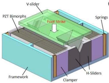
text_image
V-slider PZT Bimorphs Foot Strike Spirings Framework Clamper H-Sliders
(b)

natural_image
Top-down view of a white and blue athletic shoe with metal plates and screws (no text or symbols visible)
(c)
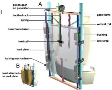
text_image
pinion gear on generator toothed rack spring linear transducer load cell load plate locking mechanism load attached to load plate A pack frame vertical rod bushing arm strap B
(d)
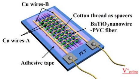
text_image
Cu wires-B Cu wires-A Cotton thread as spacers BaTiO₃nanowire -PVC fiber PET Adhesive tape V⁺_poling
(e)
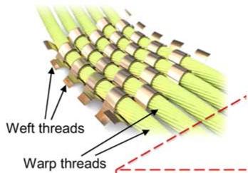
text_image
Weft threads Warp threads
(f)
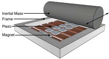
text_image
Inertial Mass Frame Piezo Magnet
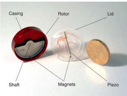
text_image
Casing Rotor Lid Shaft Magnets Piezo
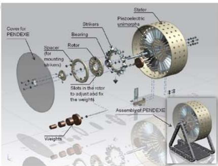
text_image
Cover for PENDEXE Spacer (for mounting shivers) Steers Rotor Stirks Piezoelectric unimorphs Slots in the rotor to adjust add for the weights Weights Assembly of PENDEXE
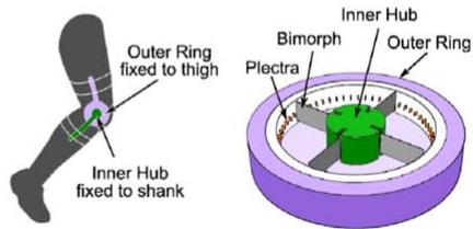
text_image
Outer Ring fixed to thigh Inner Hub fixed to shank Inner Hub Bimorph Plectra Outer Ring
Figure 12. Various piezoelectric wearable harvesters including (a) shoe harvester with a slider mechanism (reprinted from [380], with the permission of AIP Publishing), (b) shoe harvester with wavy structure (reproduced from [382]. CC BY 3.0), (c) backpack harvester (reprinted from [385], Copyright 2008, with permission from Elsevier), (d) fabric-like nanogenerator (reprinted from [386], Copyright (2015), with permission from Elsevier), (e) PVDF fabric-like harvester (reproduced from [387]. © IOP Publishing Ltd. All rights reserved), (f) snaprelease mechanism (reproduced from [388]. © IOP Publishing Ltd. All rights reserved), (g) wrist harvester (reprinted from [389], Copyright 2014, with permission from Elsevier), (h) PENDEXE waist harvester (reprinted from [390], Copyright 2015, with permission from Elsevier), and (i) knee harvester (reproduced from [391]. © IOP Publishing Ltd. All rights reserved).
Several studies have proposed various mechanisms to convert the kinetic energy of limb motion to electrical energy. One major issue in harvesting the kinetic energy of the human body is the low frequency of body motion (less than 25 Hz [390]). Piezoelectric harvesters provide the highest energy conversion efficiency in resonant mode, which is typically higher than the frequency of motion in the human body. In order to obviate this limitation, different frequency upconversion mechanisms have been suggested. Pillatsch et al in 2012 [388] suggested a piezoelectric energy harvester with multiple piezoelectric bimorphs with a tip magnet and a rolling element that passes over the beams (figure 12(f)). As a result of external motion, the rolling mass rolls over the piezoelectric beams and, because of the snap-release mechanism, the beams resonate at their natural frequency. Experimental tests showed that the device could generate 2.1 mW of power at an excitation frequency of 2 Hz. This group presented another frequency upconversion mechanism in 2014 based on a rotating mass system to supply power for a wrist watch, similar to the system commercially used in Seiko Kinetic wrist watches, but with lower friction [389]. Using an eccentric rotating proof mass with a permanent magnet and a fixed piezoelectric bimorph with a tip magnet mass, this system generated 43 μW of power at a frequency of 2 Hz (figure 12(g)). This system is compatible with linear and rotational excitation modes. Similarly, the application of a piezoelectric system as a self-powered human activity recognition system was introduced and tested by Khalifa et al in 2015 [394] to obviate the power limitation of current accelerometers. Wahbah et al in 2014 [395] also showed that a combination of thermoelectric and piezoelectric resonant harvesters can be utilized on the wrist to generate power. The impact-driven piezoelectric energy harvester proposed by Wei et al in 2013 [396] is another example of a frequency upconversion system suggested for power harvesting from human body motion. A novel design of a low frequency piezoelectric energy harvester was proposed by Shukla and Bell in 2015 [390]. A frequency upconversion system including a rotor pendulum with multiple strikers and multiple PVDF bimorphs, called PENDEXE, was designed to generate power from waist motion (figure 12(h)). Tests showed that the device could generate 290 μW of power from the very low frequency motion of the waist (2 Hz) for normal walking.
In addition to the previously mentioned applications, energy harvesting systems using wearable piezoelectric generators from knee motion, jaw movement, breathing, and the ear canal have been presented. Pozzi et al in 2012 [391] suggested a knee joint wearable piezoelectric energy harvester with four fixed piezoelectric bimorphs and 74 plectra embedded in a rotating ring (figure 12(i)). The device attached to a human knee generated 2.06 mW of power from normal walking with the frequency upconversion mechanism. Later in 2016 [397], this group improved the generated power to 5.8 mW by altering the mechanical buckling mechanism with a magnetic buckling mechanism. Delnavaz and Voix in 2014 [398] showed that a hybrid generator consisting of a very simple piezoelectric ring and an electromagnetic generator located inside the ear canal could generate of energy out of 5 mW of potentially available power. This group has also presented a piezoelectric energy harvester for power harvesting from jaw movement [399]. The system consists of a piezoelectric fiber composite plate placed under the chin and attached to a head-mounted device using two elastic rubber straps, and was found to generate of power during chewing with slight discomfort for the user. Using an integrated array of piezoelectric films and a harvesting circuit placed within a pant belt, Abdi et al in 2014 [400] showed that 1.5 mW of power could be harvested from breathing. This power was generated without any active human engagement in the process and from a very low frequency of motion of breathing (between 0.25 Hz to 0.35 Hz).
Table 5 summarizes the energy source, transducer type, generator material, dimensions, input excitation, and output power of the different wearable piezoelectric harvesters described herein. This table attempts to provide the most relevant information for comparison purposes; additional details of each study can be found within the respective manuscripts.
3.2.2. Implantable devices. The emersion of smart implantable medical devices in the past two decades has improved therapeutic and diagnostic methods to a large extent. One issue with implantable devices is the limited life time of batteries, which require intermittent replacement. In many cases, replacing the battery or device requires rigorous procedures associated with a high risk for patients. In order to tackle the current power limits of these devices, researchers have investigated implantable piezoelectric energy harvesters aimed at powering electronic devices embedded in the human body.
In 2011, Almouahed et al [401] suggested an instrumented knee replacement with four piezoelectric transducers placed in the tibial tray of the knee implant. An optimized design of the device with respect to the transducer location, material, and dimension, presented in 2016, showed that up to 4.276 mW of average power at an optimal resistive load of 50 kΩ could be obtained from a knee implant under a realistic knee load profile [402] (figure 13(a)). In a study performed by Holmberg et al in 2013 [403], a wireless self-powered sensory system was embedded inside the tibial tray of a knee replacement that utilized a piezoelectric stack which provides the required power for six capacitive force sensors. Experimental results for a 55 kg person showed that the piezoelectric harvester could harvest 1.051 mJ energy per step, which was sufficient to power the sensors, signal conditioning circuits, and wireless data transmitter with a low duty cycle. More recently, Safaei et al in 2018 [404] presented an instrumented knee replacement with four piezoelectric transducers located in the bearing of the implant for sensing knee forces and contact locations, and energy harvesting from human gait. Power harvesting test results showed that the energy generated from one hour of walking in normal conditions and stored in a capacitor was sufficient to power 9 min of sensing and data processing, and 5 s of wireless data transmission of a low-power biomedical sensing circuit published in the literature. An improved design of an instrumented knee bearing with six embedded piezoelectrics was proposed by the same group in order to measure compartmental forces and contact locations (figure 13(b)) [405]. The device was numerically optimized and experimentally validated. Result showed that the system was able to track the location of medial and lateral forces and location of contact points acting on the conforming surface of the bearing.
Currently, implantable electronic devices, such as cardiac pacemakers and cardiac monitors, are powered with embedded batteries. Due to the limited lifetime of batteries, a surgical procedure is needed to replace the batteries, which exposes the patient to a variety of risks. Piezoelectric energy harvesting provides the potential to power the implanted electronic devices with energy collected from internal organs, such as the heart, lungs, diaphragm, etc. Karami and Inman in 2012 [34] investigated energy harvesting from heartbeat vibration using a nonlinear piezoelectric energy harvester to power pacemakers. Measured heartbeat data from the literature was used to perform simulations which demonstrated that a nonlinear cantilever harvester with dimensions of could to generate over of power over a broad range of heart rates from 7 beats per minute to 700 beats per minute. This group, later in 2016 [406], utilized several device configurations including fanfolded, elephant, and zigzag configuration for heartbeat energy harvesting, and showed that the fan-folded configuration allowed the device to generate the most power (figure 13(c)). Experimental results showed that this system generated of average power, which is sufficient to power a pacemaker, and the output was robust to variation in heart rate [411]. Advantages of the system included MRI compatibility, small size, and a mechanism that was contactless with heart tissue.
Table 5. Summary of various wearable piezoelectric energy harvesting devices .
| Author | Device | Energy Source | Transducer Type | Generator Material | Dimensions | Input Excitation | Output Power |
| Xie et al [380] | Shoe insole | Human gait | Bimorph | PZT-5H | $50 \times 40 \times 23 \text{ mm}^{3}$ | Normal gait of a 68 kg, 180 cm male | 0.41 mW $\text{cm}^{-3}$ |
| Jung et al [381] | Shoe insole | Human gait | Piezoelectric sandwich | PVDF | Two $70 \times 40 \times 0.6 \text{ mm}^{3}$ curved generators | Normal gait of a 68 kg male | 25 V and 20 μA |
| Zhao et al [382] | Shoe insole | Human gait | Wavy film | PVDF | $80 \times 50 \times 3 \text{ mm}^{3}$ | 400 N at 1 Hz | 1 mW |
| Granstorm et al [392] | Backpack | Human gait | Piezoelectric strap | PVDF | — | 444 N load of backpack | 45.6 mW |
| Feenstra et al [385] | Backpack | Human gait | Piezoelectric stack with amplifier | PZT stack | — | 220 N load of backpack | 0.4 mW |
| Yang and Yun [393] | Fabric with embedded shell | Joint motion | Curved shell | PVDF | — | Elbow motion | 25 V |
| Zhang et al [386] | Fabric | Joint motion | Hybrid fiber-based fabric | $BaTiO_{3}$ Nanowires | — | Elbow motion | 10.02 nW |
| Song and Yun [387] | Fabric | Joint motion | Fabric textile | PVDF | — | 1.23 stretch ratio at 6 Hz | 125 μW $\text{cm}^{-2}$ |
| Pillatsch et al [388] | Impulse-excited harvester | Limb motion | Bimorph | PZT 507 | — | Rotation at 2 Hz | 2.1 mW |
| Pillatsch et al [389] | Wrist watch | Limb motion (arm) | Bimorph | M1100 piezoceramic | 30 mm diameter, 7 mm thickness | Rotation at 2 Hz | 43 μW |
| Shukla and Bell [390] | PENDEX | Limb motion (waist) | Unimorph | PVDF | — | Normal walking at 2 Hz | 290 μW |
| Pozzi et al [391] | Knee harvester | Joint motion (knee) | Bimorph | PZT-5H | — | Normal walking | 2.06 mW |
| Kuang et al [397] | Knee harvester | Joint motion (knee) | Piezomagnetic generator (bimorph) | PZT5-H | — | Normal walking | 5.8 mW |
| Delnavaz and Voix [399] | Hybrid piezoelectric-electro-magnetic harvester | Jaw movement | Piezoelectric strap | Piezoelectric fiber composite | — | Stretch ratio of 1.2 during chewing | 7 μW |
| Abdi et al [400] | Piezoelectric belt | Abdominal motion (breathing) | Layered films | PVDF | — | Breathing at 0.35 Hz | 1.5 mW |
(a)
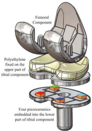
text_image
Femoral Component Polyethylene fixed on the upper part of tibial component Four piezoceramics embedded into the lower part of tibial component
(b)
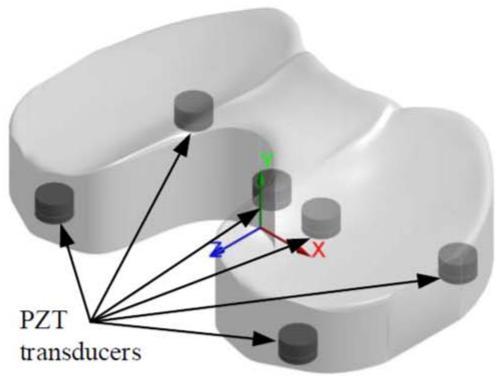
text_image
PZT transducers
(c)
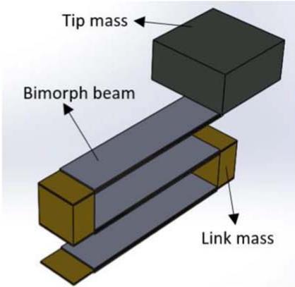
text_image
Tip mass Bimorph beam Link mass
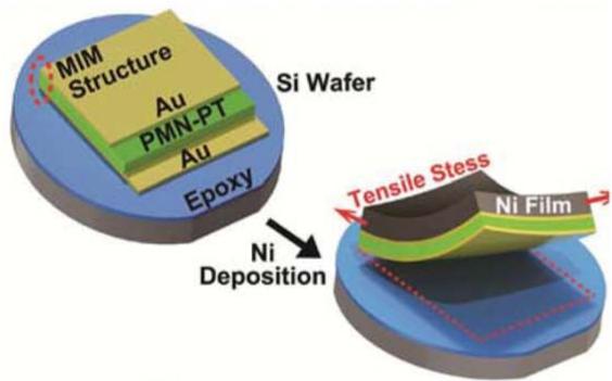
text_image
MIM Structure Au PMN-PT Au Epoxy Si Wafer Ni Deposition Tensile Stress Ni Film
(e)
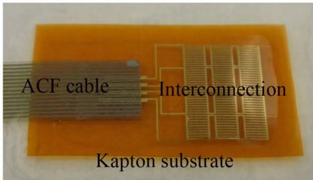
text_image
ACF cable Interconnection Kapton substrate
(f)
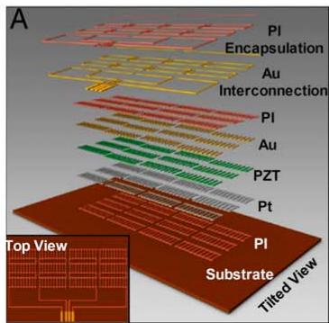
text_image
A PI Encapsulation Au Interconnection PI Au PZT Pt PI Substrate Tilted View Top View
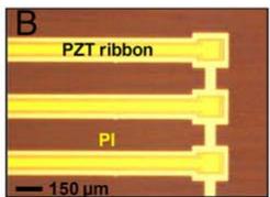
text_image
B PZT ribbon PI 150 µm
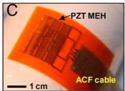
text_image
C PZT MEH ACF cable 1 cm
(g)
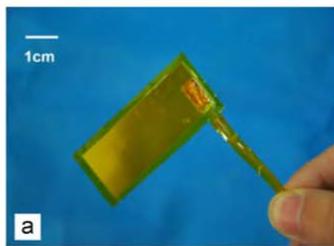
natural_image
Close-up of a hand holding a small yellow object against a blue background, with a 1cm scale bar for size reference (no text or symbols on the object itself)
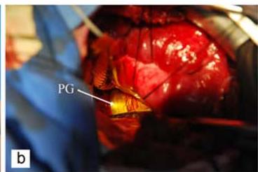
text_image
PG b
Figure 13. Various implantable piezoelectric harvesters including (a) instrumented knee tibial tray (© 2016 IEEE. Reprinted, with permission, from [402]), (b) instrumented knee bearing (copyright [405] 2018. Society of Photo Optical Instrumentation Engineers), (c) fanfolded heart harvester (reprinted from [406], with the permission of AIP Publishing), (d) PMN-PT-based flexible heart harvester ([407] John Wiley & Sons. © 2014 WILEY‐VCH Verlag GmbH & Co. KGaA, Weinheim), (e) PZT-based flexible heart harvester (reproduced from [408]. CC BY 4.0), (f) multilayer PZT flexible harvester (reproduced with permission from [409]), and (g) aorta harvester (reprinted from [410], Copyright 2015, with permission from Elsevier).
Several researchers have proposed various designs of flexible energy harvesters for power generation from cardiac motion. Hwang et al in 2014 [407] utilized a flexible single crystalline PMN-PT piezoelectric energy harvester to develop a self-powered cardiac pacemaker (figure 13(d)). Using PMN-PT with a piezoelectric strain constant of pC (almost four times more than PZT and twenty times more than , the implemented device placed in the cardiac muscle of a live rat showed a relatively high output current of 0.223 mA and output voltage of 8.2 V. Similarly, in 2015, Lu et al [408] developed an ultra-flexible PZT energy harvester to be integrated with the heart. The device was fabricated using transfer printing technology by applying PZT film between extremely soft substrate layers and implanted in a swine (pig) heart for in vivo testing (figure 13(e)). The effects of various suture fixation, mounting locations, and orientations were investigated in open/close chest and anesthesia/conscious conditions. A 3 V peak to peak generated voltage from this generator was found experimentally and is sufficient to power a cardiac pacemaker.
In an exceptional work, Dagdeviren et al in 2014 [409] applied several advanced material and engineering processes to develop a biocompatible and flexible piezoelectric energy harvester. A multilayer PZT structure was encapsulated in biocompatible material (polyimide) to minimize the risk of failure or immune system response (figure 13(f)). The device was evaluated in cell cultures, on large-scale, live animal models using various locations and orientations, and on different organs including the heart, lungs, and diaphragm. Adequate energy to power a pacemaker was obtained from the experiments, and the biocompatibility, mechanical properties, and electrical properties were tested for 20 million cycles under moist and hydrogel environment. More recently, Jeong et al in 2017 [412] fabricated a flexible harvester based on a lithium niobate -doped KNaNbO (KNN) lead-free piezoelectric thin film and implanted it into a porcine (pig) chest. In vivo tests showed that the harvester could generate up to 5 V and 700 nA from the heartbeat.
In a study presented by Deterre et al in 2014 [413], a very small piezoelectric energy harvester was developed for power generation from ordinary blood pressure variations to power a leadless pacemaker. The device was a microfabricated spiralshaped piezoelectric beam within an ultra-flexible packaging equipped with a 10 μm diaphragm. The harvester had a diameter of 6 mm and volume of . Experimental results from an optimized design of the device showed a power density of per heartbeat. The application of a sealed, flexible PVDF film for energy harvesting from pulsation of the ascending aorta of the heart was suggested by Zhang et al in 2015 [410] (figure 13(g)). Several experiments were performed to investigate the in vitro, in vivo, and sealing performance of the suggested flexible, implantable piezoelectric generator. The results showed that 681 nW and 30 nW were generated from in vitro and in vivo experiments, respectively, and the sealing package successfully prevented the device from being penetrated by saline water. The authors note that further optimization is needed on this design to improve the performance of the piezoelectric generator.
In the work of Jang et al in 2015 [414], a conceptual design of a piezoelectric artificial basilar membrane (ABM) was developed to be used as the front end of a cochlear implant. The fabricated prototype incorporated an array of eight piezoelectric cantilevers with a frequency range of 2.92 to 12.6 kHz. The results of their work demonstrated the feasibility of using the piezoelectric ABM for frequency separation. Following the work of Jang et al, the design of a fully-implantable cochlear implant using an array of thin film piezoelectric acoustic transducers was presented by Ilik et al in 2018 [415]. The system consisted of an array of piezoelectrics cantilevers designed to be placed on the eardrum or ossicles to generate the signal for neural stimulation. Eight piezoelectric cantilevers were placed facing each other with various lengths to result in a small size of . Each cantilever was designed to cover a specific frequency range of acoustic sound pressure. Acoustic tests on a fabricated prototype of the harvester showed that a peak-topeak voltage of 114 mV could be generated at a sound pressure level of 110 dB, which satisfies the power requirements of an implantable cochlear implant for stimulating the auditory nerves.
Table 6 summarizes the energy source, transducer type, generator material, input excitation, verification method, and output power of the different wearable piezoelectric harvesters described herein. This table attempts to provide the most relevant information for comparison purposes; additional details of each study can be found within the respective manuscripts.
3.3. Energy harvesting from animals
The relatively small size of most avian animals, such as flying insects and birds, constrains the size and mass of data loggers and tracking devices developed to collect data from their activities. Due to this limitation, the allowable size and mass of on-board batteries, and as a result, their total power and lifetime, have also been highly curbed. Researchers have recently introduced the concept of energy harvesting in wildlife to create autonomous, living, micro air vehicles (MAVs) that can be controlled, where the harvester can provide the required power for animal tracking and bio logging devices.
An extensive study was initiated at the University of Cornell in 2008 by Dr. Garcia’s research group on the feasibility of power generation from avian sources. Initial studies on flying insects showed that three sources of energy are available at milligram and miniature-scale including solar, thermal, and kinetic energy [416]. Although solar energy presented a higher harvestable power density than the other sources, kinetic energy is less affected by environmental conditions and, therefore, is continuously available. Experimental measurements of the available energy and forces as a result of the flapping motion of insect flight showed that about 40 mW of muscle energy is available and half to one-third of the mass of the insect can be loaded on the insect without affecting the stability of flapping [417]. First proposed by Reissman and Garcia in 2008 [418], the possibility of harvesting vibration energy during flight of a moth using piezoelectric materials was investigated. The concept of surgically adding energy harvesting and storage elements as well as neurological control capability to the insect during the pupa phase of development (prior to becoming an adult moth) was discussed. Piezoelectric generators were suggested to scavenge the kinetic energy of insects during flight [419]. Experimental studies showed that of power was generated from the implemented piezoelectric energy harvester having a mass of 0.292 g on a hawkmoth in an untethered flight condition, which was sufficient to power an LED with 196 mW of power consumption every 2 s for a duration of 29 μs [420] (figure 14(a)).
In a similar study inspired by the idea of hybrid insect vehicles, Aktakka et al in 2011 [421, 423] presented a nonresonant piezoelectric device to harvest energy from a live insect (Green June Beetle) with a body mass of 1.3 g and an average size of . Initially, the available energy from different body parts of the beetle was measured using a piezoelectric bimorph during tethered flight and the wing base, which demonstrated of power generation, was chosen. Two backpack-type PZT bimorph harvester designs were introduced and a maximum power density (power/ weight) of was generated during a tethered flight by a design consisting of two miniature beams attached to a location near the base of the wings. An improved harvester design including two spiral piezoelectric beams with dimension of weighing less than 0.2 g was also introduced and the device was able to generate about 45 μW of power during flight of the Green June Beetle (figure 14(b)).
Table 6. Summary of various implantable piezoelectric energy harvesting devices .
| Author | Device | Energy Source | Transducer Type | Generator Material | Input Excitation | Verification Method | Output Power |
| Almouahed et al [402] | Piezoelectric tibial tray | Knee motion | Stack | NCE51 (PZT-5A) | Normal gait | In vitro test | 4.27 mW |
| Holmberg et al [403] | Battery-less knee implant | Knee motion | Stack | TS18-H5-104 | Normal gait | In vitro test | 1.051 mJ per step |
| Safaei et al [404] | Piezoelectric bearing | Knee motion | Stack | NCE51 (PZT-5A) | Normal gait | In vitro test | 269.1 μW |
| Ansari and Kar-ami [411] | Fan-folded harvester | Heartbeat | Fan-folded structure | PSI-5A4E (PZT-5A) | 20-100 bpm heartbeat | In vitro test | 15.2 μW |
| Hwang et al [407] | Flexible single crystal-line harvester | Heartbeat | Piezofilm adhered on a flexible substrate | PMN-PT | Rat heartbeat | In vivo test | 0.223 mA and 8.2 V |
| Lu et al [408] | Ultra flexible energy harvester | Heartbeat | Printed PZT layers | PZT | Swine (pig) heartbeat from 21 to 125 bpm | In vivo test | 3 V |
| Dagdeviren et al [409] | Mechanical energy harvester | Heart, lung, diaphragm | Encapsulated PZT ribbons | PZT | Bovine (cow) heartbeat | In vivo test | 1.2 μW cm-2 |
| Jeong et al [412] | Flexible energy harvester | Heart | Thin film | KNN | Porcine (pig) heartbeat | In vivo test | 5 V and 700 nA |
| Zhang et al [410] | Piezoelectric generator | Heartbeat | Piezoelectric Film | PVDF | Pulsation of ascending aorta of a porcine (pig) | In vitro and In vivo tests | 30 nW |
| Ilik et al [415] | Cochlear harvester | Vibration of eardrum | Piezoelectric thin film | PZT | Sound pressure of 110 dB | In vitro test | 114 mV |
(a)

natural_image
Close-up of a moth with yellow and brown markings resting on a white surface, next to a ruler for scale (no text or symbols visible)

natural_image
Close-up of a hand holding a small bird’s head with a small electronic device attached to its wing (no visible text or symbols)
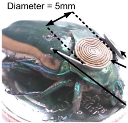
text_image
Diameter = 5mm
Figure 14. Various piezoelectric energy harvesting systems from animals including (a) piezoelectric beam on a hawkmoth (reproduced with permission from [420]), (b) backpack-type harvester on a beetle (reproduced from [421]. © IOP Publishing Ltd. All rights reserved), and (c) piezoelectric beam harvester on a Western Sandpiper (reproduced with permission from [422]).
Later in 2012, Shafer et al [422] investigated the possibility of energy harvesting from birds in order to power active wildlife monitoring tags (figure 14(c)). The stored energy can be used to collect environmental data, location data, transmit stored data, and take in-situ physiological measurements of the bird. To this extent, the safely harvestable power from a bird was calculated and, using recorded flight acceleration measurements, an appropriately sized piezoelectric energy harvester was proposed. It was shown that birds can carry up to 4% of their body mass safely. It was also theoretically calculated that a power of up to 5 mW can be harvested from bird flight (0.5 kg bird), which decreased with a decrease in the weight of the bird. From acceleration measurements, it was observed that there was only a slight dependence on the flapping frequency and flapping intensity which was important for designing a harvester with single resonant mode operation. The flapping frequencies of two birds were measured between 11.5 to 14.5 Hz and the magnitude of acceleration of the birds in flight was on the order of 1.5–1.75 g. In another work in 2015 [424], this group extended the study to a variety of North American birds and bats and performed a series of experimental tests on a fabricated piezoelectric bimorph harvester with a tip mass. They showed that for a large bird (Canadian goose with 10 kg mass), the transducer can harvest 20–200 mW of power, and for a small bird with 10 g mass, the transducer can harvest of power. In particular, a 1.6 g harvester installed on a 40 g Swainson’s thrush showed an output power of at a flapping frequency of 12 Hz. Considering a typical bio-logger, the energy harvester was able to provide sufficient power while requiring only modest activity from the host. In addition to avian subjects, the potential application of energy harvesting from marine animals using the fluid flow associated with swimming or the pressure energy available when the animal dives was introduced by this research group in 2014 [425] in order to prolong the life of the tags that compile data about the animals and their environment.
Table 7 summarizes the device, energy source, transducer configuration, generator material, dimensions/mass, test condition, and output power of the different animal-based piezoelectric harvesters described herein. This table attempts to provide the most relevant information for comparison purposes; additional details of each study can be found within the respective manuscripts.
Table 7. Summary of various piezoelectric devices for energy harvesting from animals .
| Author | Device | Energy Source | Transducer Configuration | Generator Material | Dimensions/Mass | Test Condition | Output Power |
| Reissman et al [420] | Piezoelectric beam | Hawkmoth | Unimorph | PZT-5H | 0.292 g | Untethered flight | 59 μW |
| Aktakka et al [421] | Two miniature beams | Green June Beetle | Bimorph | PZT-5H | 380 μm thick beam 5.6 mm $^{3}$ | Tethered flight | 7.5 μW |
| Aktakka et al [421] | Backpack-type harvester | Green June Beetle | Spiral piezoelectric beams | PZT-5H | 6 × 6 mm $^{2}$ 0.2 g | Tethered flight | 45 μW |
| Shafer et al [424] | Birds harvester | A 40 g bird | Bimorph | PZT-5A | 1.6 g | Untethered flight at 12 Hz flapping frequency | 250 μW |
3.4. Energy harvesting in infrastructure
The complexity of energy management in cities along with recent developments in technologies for monitoring infrastructure and buildings has led researchers to investigate the feasibility of energy harvesting from manmade infrastructure. Bridges, buildings, and roads provide promising vibrational energy content for piezoelectric energy harvesting due to wind, vehicle motion, and human traffic, which can be converted to usable electric energy. The harvested energy can be used to power nearby systems, such as wireless sensor networks that provide information about road conditions, traffic weight and pattern, and vehicle speeds, or other electronic systems.
In the study performed by Li and Strezov in 2014 [426], the potential of using a commercial piezoelectric energy harvester tile in buildings with high pedestrian traffic was investigated. The tiles were considered for installation in a university library building in Sydney, Australia. The high cost of the piezoelectric power generation tiles ($3850/tile) limited the application of these tiles. The tiles are manufactured by Pavegen and are designed to harvest kinetic energy from footsteps. The work included a series of statistical studies to determine high traffic areas, the number of expected pedestrians, and an estimation of the generated power. According to the results obtained from the optimized tile model, 1.1 MWh/ year of power can be potentially obtained from pedestrians. It was estimated that the power can be increased to 9.9 MWh/ year by employing a plucked harvester design (two-stage design), which is about 0.5% of the total electricity usage of the building. Hwang et al in 2015 [427] presented a piezoelectric footstep energy harvester consisting of an upper plate, a middle plate with piezoelectric modules, and a fixed bottom plate with four supporting springs (figure 15(a)). The piezoelectric modules contain four cantilever beams with tip masses that are attached to the upper plate. An impedance matching technique was utilized to optimize the extracted power, and of RMS power and 55 mW of peak power was experimentally obtained from the design, which is 203% more than the energy harvested from a shoe [428].
In 2013, Xie et al [435] introduced the application of piezoelectric energy harvesters in power generation from high-rise buildings under dynamic wind and earthquake loading. The harvester employs the oscillation of a tuned mass damper in order to generate power from dissipating energy. The tuned mass is attached to a vertical cantilever column with piezoelectric patches. An optimized design of the harvester with respect to several parameters, such as thickness ratio of the piezoelectric to cantilever, length and location of the piezoelectric patch, mass, and radius of the mass, showed a theoretical maximum power conversion efficiency of up to 28%. Two years later, the same group presented a piezoelectric harvester device to generate power from oscillation of a proof mass attached to a vertical cantilever beam placed on the roof of a high-rise building [429]. Two ring-type piezomagnetic harvester groups connected by a shared shaft and a linking rod hinged on the proof mass comprised the power generation unit (figure 15(b)). The developed analytical model showed that an optimized harvester design could generate 432.21 MW of RMS power under special high frequency seismic building motion.
In addition to buildings, energy harvesting from vehicle traffic-induced vibration has been investigated by several researchers. Energy harvesting from pavement deformation under moving traffic using a piezoelectric generator was investigated by Xiang et al in 2013 [436]. Using an infinite Euler-Bernoulli beam resting on a Winkler foundation, the velocity of the vehicle, foundation modulus of elasticity, and damping of the system were analytically determined to be the most effective factors on energy harvesting performance. For a vehicle with velocity of 108 km (67 mph), the peak value of power generated by a piezoelectric patch with the dimension of was 0.501 W obtained across a matching resistive load of 500 kΩ. In another work, Jiang et al in 2014 [430] presented a novel compression-based piezoelectric energy harvester to harvest power from roadway traffic. The harvester consisted of a platform equipped with three piezoelectric harvester units. Vehicles pass over the platform as a part of the road. Each unit consisted of three piezoelectric multilayer stacks located in a circular arrangement (figure 15(c)). A lab-scale prototype of the device was fabricated and tested with a shake table to verify the analytical model developed for the system. Using the verified model, a maximum power of 2000 W h−1 was estimated to be harvested from highway traffic with 2000 vehicles/h having 100 km h−1 (62 mph) average velocity (or 1 W DC power per passing vehicle).
In another attempt to generate power from moving vehicles, Moure et al in 2016 [437] developed a piezoelectric cymbal device to be embedded in asphalt. Cymbal transducers have good characteristics for this application due to their high flexibility and strength. A cymbal design with two metal caps and a PZT ceramic was optimized in order to find the best performance during asphalt integration. The final cymbal design with a radius of 30 mm was fabricated and embedded in a mastic host layer of bitumen and silica fiber placed between two different pavement layers for experimental tests. Simulations on the chosen pattern of 3 cymbals connected in series and placed transverse to the direction of car movement under 2 cm of asphalt with the optimized composition showed that 16 of power could be generated from each cymbal. Considering 100 m of road with 30 000 embedded cymbals, a total energy of 65.8 MWh/year for a year can be generated. Cost analysis of the system showed that the harvesting system could provide 10% of the required energy of Madrid, Spain with only 0.6% of roads in this region having embedded harvesters. Based upon traditional cymbal transducers, a novel bridge transducer design was suggested by Jasim et al in 2017 [431] for energy harvesting from moving vehicles in roadways. They designed a new poling pattern and electrode configuration to change the direction of polarization in order to utilize the axial piezoelectric coefficient under axial applied stress, including seven sections of piezoelectric cells connected in parallel (figure 15(d)). An optimal harvester design is achieved using multiphysics numerical simulation considering the compromises between harvesting performance and potential of mechanical failure. Laboratory test results illustrated that the bridge transducer generated four times more energy and energy efficiency compared to a traditional bridge transducer due to having the applied stress in the direction of polarization. A maximum power of 2.1 mW was obtained with a 400 kΩ load resistance at 5 Hz excitation and under 70 kPa applied pressure for 64 bridge transducers. Note, road tests are still required to obtain the realistic system performance.
(a)
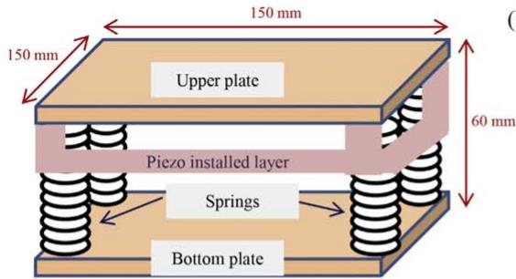
text_image
150 mm Upper plate Piezo installed layer Springs Bottom plate 60 mm
(b)
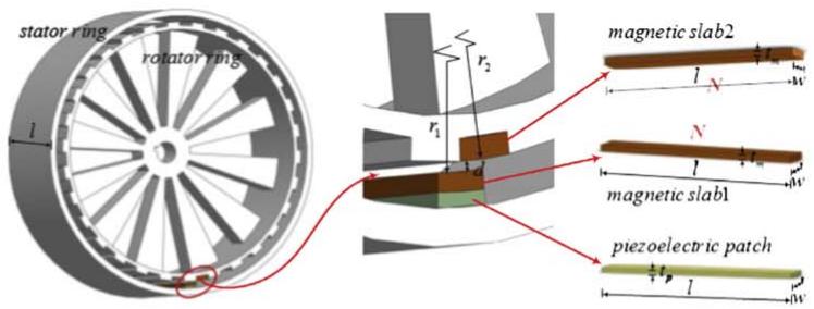
text_image
stator ring rotator ring l r2 r1 d magnetic slab2 l N N l magnetic slab1 piezoelectric patch ½tp l w
(c)
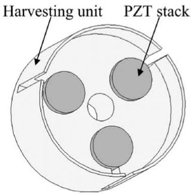
text_image
Harvesting unit PZT stack
(d)
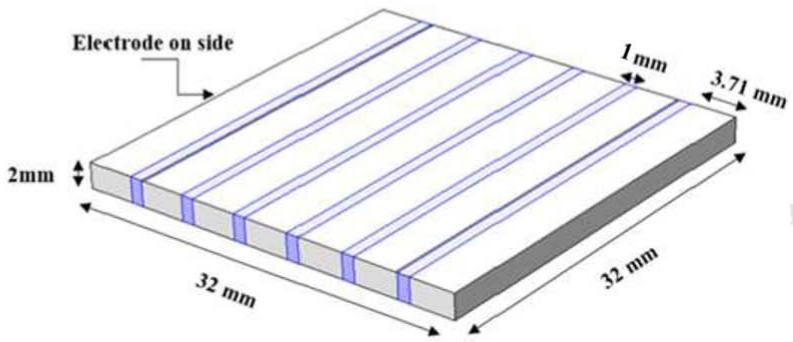
text_image
Electrode on side 2mm 32 mm 1 mm 3.71 mm 32 mm
(e)
natural_image
Close-up of a mechanical device with wires and a digital display showing measurement (no readable text or symbols)
(f)
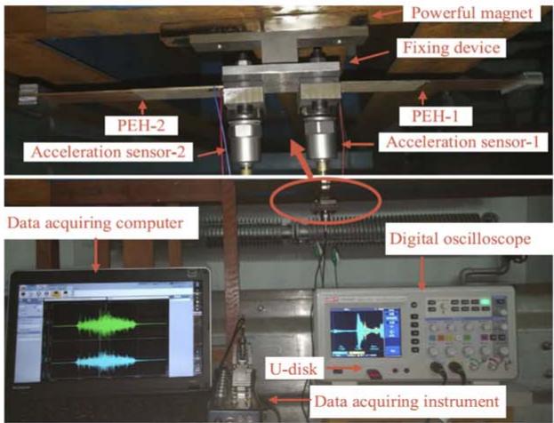
text_image
Powerful magnet Fixing device PEH-2 PEH-1 Acceleration sensor-2 Acceleration sensor-1 Data acquiring computer Digital oscilloscope U-disk Data acquiring instrument
(g)
6sets ofharvesters (60 ea)
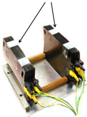
natural_image
Mechanical assembly with copper housing and yellow connectors, no visible text or symbols
Figure 15. Various energy harvesting devices designed for infrastructure including (a) footstep harvester (reprinted from [427], Copyright 2015, with permission from Elsevier), (b) ring-type piezomagnetic harvester (reprinted from [429], Copyright 2015, with permission from Elsevier), (c) road traffic harvester (reprinted from [430], with the permission of AIP Publishing), (d) bridge harvester (reprinted from [431], Copyright 2017, with permission from Elsevier), (e) bridge traffic harvester (reproduced from [432]. © IOP Publishing Ltd. All rights reserved), (f) bridge traffic harvester (reprinted from [433], Copyright 2018, with permission from Elsevier), and (g) roadway harvester (reprinted from [434], Copyright 2017, with permission from Elsevier).
The application of piezoelectric energy harvesting from the vibration of bridges due to traffic induced vibration was suggested by Peigney and Siegert in 2013 [432]. Initially, the vibration characteristics of a case study bridge in France at different source locations were studied using several accelerometers. Generally, traffic induced vibration in bridges is low frequency and contains small amplitudes, therefore, energy harvesting is a challenging task even for measuring slow time-varying signals such as temperature or humidity. Based on experimentally collected vibration data, a piezoelectric bimorph cantilever harvester with a 12 g tip mass and Mide QP20W piezoelectric patches bonded at the clamped end was developed and tuned to match the dominant bridge vibration frequency at specified locations (figure 15(e)). Experimental measurements showed that 0.03 mW of power could be collected from the random short time pulse train of vehicles crossing the bridge at peak traffic intensity using a single harvester. The energy can be utilized to power wireless health monitoring sensor nodes as well as weight in motion (WIM) sensors with low duty cycle. Zhang et al in 2018 [433] investigated the energy harvesting performance of piezoelectric bimorphs tuned to the natural frequency of bridges and of coupled vehicle-bridge systems (figure 15(f)). A smallscale experimental setup was designed to mimic realistic bridge and bridge-vehicle vibration. PZT-5H piezoelectric cantilevers with dimensions of and 27 g tip masses were placed on different locations on the bridge. The optimized harvester with a resonant frequency matching the vehicle-bridge coupled natural frequency and a 60 kΩ load resistance showed that 0.53 mW of power could be generated from one harvester when a single vehicle passes the bridge at 8.3 km (5.1 mph). Jung et al in 2017 [434] proposed a PVDF energy harvester for roadway applications which presents an energy conversion performance comparable to piezoelectric ceramic-based harvesters. The device consists of 6 sets of pre-curved bimorph harvester units (figure 15(g)). The device, with overall dimension of and vertically aligned harvester units, generates 200 mW of power across a 40 kΩ load resistor for a vehicle speed of 8 km mph) and load of 490.5 N in modeled roadway testing in the laboratory.
Table 8 summarizes the infrastructure type, energy source, transducer type, generator material, dimensions, input excitation, and output power of the different infrastructurebased piezoelectric harvesters described herein. This table attempts to provide the most relevant information for comparison purposes; additional details of each study can be found within the respective manuscripts.
3.5. Energy harvesting from vehicles
Energy dissipation in different components of vehicles, in particular, the suspension system, is an important factor reducing the fuel efficiency of vehicles. It has been reported that only 10% to 16% of fuel energy is used to run the car against road friction and air drag. The idea of utilizing the waste energy of cars has led researchers to investigate the feasibility of energy harvesting from the vehicle suspension system and tires, which contain rich vibration and force profiles.
One of the initial works on energy harvesting from the deflection of vehicle tires was carried out by Khameneifar and Arzanpour in 2008 [438]. The approximated available energy of tire deflection for an average passenger car was found to be 1040–1100 W. Fourteen commercial piezoelectric resonators with dimension of each were placed inside the tire (figure 16(a)). An individual power of 3 mW and total power of 42 mW were analytically obtained for normal operation of the vehicle with the embedded energy harvester system working on the first resonant mode. In another work, Singh et al in 2012 [439] investigated the feasibility of using an inertial vibrating energy harvester to power a sensor module for tire use. A piezoelectric device consisting of a bimorph cantilever with high density PZT-ZNN piezoelectric layers and two mechanical stoppers to ensure limited mechanical strain was introduced in order to generate power from radial vibrations of the tire (figure 16(b)). The key design parameters considered in the design of the device include broadband operation, low weight, and small volume. The dimensions of the beam are with a 11.4 g tip mass. A power of 31 μW across a resistive load of 330 kΩ was obtained at 80 Hz and RMS base excitation. In order to provide broadband performance, an artificial neural network (ANN)- based closed loop system that considers the operating conditions including pressure, load, and speed was developed to ensure matched load impedance. Extensive road tests were performed under a wide range of operating conditions to train the neural network. Experimental results showed that the ANN system was able to predict the harvester operation frequencies and the corresponding matched electrical impedance to maximize the power output of the harvester across the full range of tire operating conditions.
In addition to resonance-based harvesters, various patchtype piezoelectric harvester designs have been proposed in the literature. Van den Ende et al in 2011 [444] used a piezoelectric patch attached inside a tire to harvest the strain energy from the contact area of the tire and the ground. A PZTpolymer composite material was fabricated by applying a mixture of a urethane casting resin and PZT-5A powder on a polyethylene terephthalate film substrate with a gold electrode. Several composites using granular and fiber PZTs were fabricated and the short fiber composites provided an estimated power of at a speed of 50 km (31 mph). Makki and Pop-Iliev in 2012 [440] presented energy harvesting from vehicle tires in order to power tire pressure monitoring sensors using two harvester designs. The first design is a piezoelectric bender bonded to the inner surface of the tire (figure 16(c)), and the second design is a smaller and stiffer element located on the tire bead and rim interface that generates energy as a result of sudden compressive forces. It has been noted by the authors that the second design requires further improvements to be applicable. PZT discs of 25 mm diameter and 0.1 mm thickness are used for the first design. Experiments showed that the first harvester can power a sensory and data transmission system every 6 s at vehicle speeds of 10 km mph) and every 1 s at vehicle speeds of 60 km mph). Lee and Choi in 2014 [445] developed another piezoelectric nonresonant system to harvest energy from vehicle tires and to power wireless sensors (strain gauges and a data transmitter) placed inside the tire. Maintaining the harvesting performance for low driving speeds and the structural stability for higher speeds were defined as requirements of the system. A piezoelectric flexible composite consisting of piezoelectric fibers, interdigitated electrodes, and a flexible substrate was installed inside the tire, and the performance of the system was investigated both analytically and experimentally. A power density of mm−3 (even with about 90% energy loss in circuit) was obtained from the system. The power was sufficient to supply energy for the wireless sensory system. Another piezoelectric composite harvester design for energy harvesting from car tires was suggested by Xie and Wang in 2015 [441]. The suggested piezoelectric tire consisted of several layers including a layer of tire tread and two steel belts, with a piezoelectric ring of PZT4 patches embedded in a polymer ring placed in between. The sandwiched piezoelectric ring was tightly adhered in the inner liner of the tire (figure 16(d)). A dual mass model of the harvester, tire, and one quarter of the car showed that an optimized configuration could generate up to 42.08 W of RMS power at a vehicle speed of 144 km (90 mph).
Table 8. Summary of various piezoelectric devices for energy harvesting from infrastructure.
| Author | Device | Infrastructure Type | Energy Source | Transducer Type | Generator Material | Dimensions | Input Excitation | Output Power |
| Li and Stre-zov [426] | Piezoelectric tile | Buildings | Pedestrian traffic | Commercial Pavegen tile | — | $600 \times 450 \times 82 \text{ mm}^{3}$ , one tile | 178 tiles, 26 188 people count | 1.1 MWh/year |
| Hwang et al [427] | Piezoelectric tile | Buildings | Pedestrian traffic | Bimorph | PZT-PZNM | $150 \times 150 \text{ mm}^{2}$ , one tile | 68 kg man, one step, one tile | 770 μW RMS power |
| Xie et al [429] | High-rise buildings harvester | Buildings | Wind and earthquake | Patch | PZT-4 | Four rings of 0.8 m wide, 3 m diameter | 1 m seismic at 30.5 rad sec $^{-1}$ | 432.21 MW |
| Xiang et al [436] | Pavement harvester | Roads | Vehicle traffic | Patch | PZT-5H | $1 \times 1 \times 0.1 \text{ cm}^{3}$ | 10.5 kN vehicle at 108 km h $^{-1}$ | 0.501 W |
| Jiang et al [430] | Compression-based harvester | Roads | Vehicle traffic | Stack | PZT-8 | — | 2000 vehicle/h at 100 km h $^{-1}$ | 2000 W h $^{-1}$ |
| Moure et al [437] | Cymbal harvester | Roads | Vehicle traffic | Cymbal | NCE51 (PZT-5A) | 30 000 cymbals of 30 mm diameter | 6565 vehicles/h at 100 km h $^{-1}$ | 65.8 MWh/year |
| Jasim et al [431] | Bridge transducer | Roads | Vehicle traffic | Cymbal-like | PZT-5X | 64 transducers of $177.8 \times 177.8 \times 76.5 \text{ mm}^{3}$ | 70 kPa at 5 Hz | 2.1 mW |
| Peigney and Siegert [432] | Bridge traffic harvester | Bridges | Wind and vehicle traffic | Bimorph | QP20W QuickPack | $40 \times 220 \times 0.8 \text{ mm}^{3}$ | 8000 vehicle/day | 0.03 mW |
| Zhang et al [433] | Bridge traffic harvester | Bridges | Wind and vehicle traffic | Bimorph | PZT-5H | $100 \times 30 \times 1.4 \text{ mm}^{3}$ | Single vehicle at 8.3 km h $^{-1}$ | 0.53 mW |
| Jung et al[434] | Roadway harvester | Roads | Vehicle traffic | Thin film | PVDF | $150 \times 150 \times 90 \text{ mm}^{3}$ | Single vehicle at 8 km h $^{-1}$ | 200 mW |
(a)
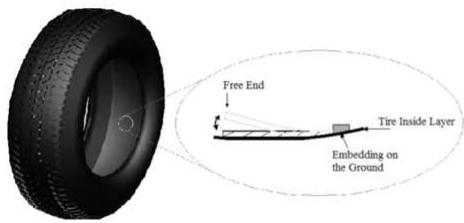
text_image
Free End t Tire Inside Layer Embedding on the Ground
(b)
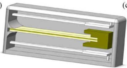
natural_image
3D diagram of a rectangular device with internal yellow and green components, no visible text or symbols
c)
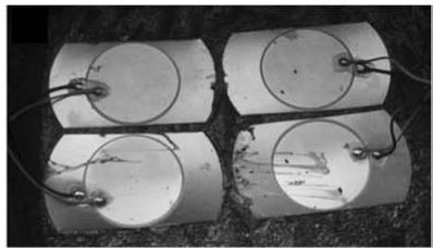
natural_image
Four identical cylindrical electronic components with wires and circular contacts, placed on a textured surface (no visible text or symbols)
(d)
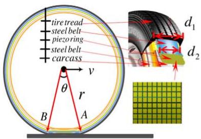
text_image
tire tread steel belt piezoring steel belt carcass v θ r B A d₁ d₂
(e)
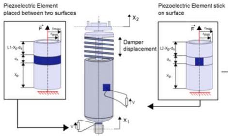
text_image
Piezoelectric Element placed between two surfaces L1-Xp-0.5 x0 F+ fmax fmax x2 Damper displacement Piezoelectric Element stick on surface L2-Xp-0.5 x0 F+ fmax fmax x1
(f)
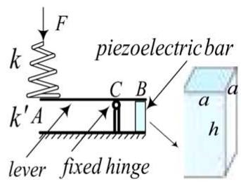
text_image
F k piezoelectric bar k’A C B lever fixed hinge a h a
Figure 16. Various piezoelectric harvester designs for energy harvesting form vehicles including (a) tire resonant harvester (reproduced with permission from [438]), (b) inertial vibrating harvester (reprinted from [439], Copyright 2012, with permission from Elsevier), (c) piezoelectric bender patch (reprinted by permission from Springer Nature: [Springer] [Microsystem technologies] [440] © 2012), (d) tire composite harvester (reprinted from [441], Copyright (2015), with permission from Elsevier), (e) suspension cylinder harvester (reprinted from [442], Copyright (2015), with permission from Elsevier), (f) suspension spring harvester (reprinted from [443], Copyright 2015, with permission from Elsevier).
Vehicle suspension systems, which contain high force and mechanical vibration content, have attracted the attention of researchers for implementation of piezoelectric energy harvesting devices in vehicles. Lafarge et al in 2015 [442] suggested the application of piezoelectric transducers on the car’s suspension system to provide energy to power microelectronics. PZT transducers in cylindrical and patch configurations were located under the car damper and on the damper surface, respectively (figure 16(e)). A dual mass model of the system showed that the former configuration outperforms the later one with a maximum power of 0.5 mW obtained at a speed of 30 km h−1 (18.6 mph), which is sufficient to power a miniaturized microcontroller system with a power consumption around 100 . In a work by Xie and Wang in 2015 [443], another piezoelectric energy harvester concept for power generation from the vehicle suspension system was suggested. In the design of the device, the suspension spring is connected to a lever and a fixed hinge transfers the moment applied by the spring to a piezoelectric bar in the form of tensile and compressive axial loads (figure 16(f)). An RMS power of 738 W was developed from a dual mass quarter car model considering the harvesting system for a vehicle under random excitation from road roughness at a speed of 126 km (78 mph). The harvesting element was a PZT4 bar with dimension of 100 × .
Table 9 summarizes the energy source, transducer configuration, generator material, dimensions, car speed/excitation, and output power of the different vehicle-based piezoelectric harvesters described herein. This table attempts to provide the most relevant information for comparison purposes; additional details of each study can be found within the respective manuscripts.
3.6. Multifunctional energy harvesting
Traditional piezoelectric energy harvesting systems are designed to produce electrical energy for powering small electronic devices, however do not offer additional function. These devices can be considered to be ad-hoc in nature or add-on components to a host structure without consideration of the behavior of the host structure, often causing undesirable mass loading effects and consuming valuable space. The concept of a multifunctional energy harvesting system is such that the energy harvesting element or device should simultaneously provide some additional capacity such as storing the scavenged energy or supporting mechanical load in the structure.
In 2010, Anton et al [446] developed a multifunctional approach to vibration energy harvesting by combining piezoelectric material with a thin-film battery for energy storage. The self-charging structures had the capacity to simultaneously harvest vibration energy and subsequently store it in the battery layers, thus creating a single device that could both harvest and store electrical energy. This selfcharging structure concept was later applied by Anton et al in 2012 [29] to the formation of a multifunctional energy harvesting system for unmanned aerial vehicles (UAVs) through integration into a UAV wing spar. The design was implemented such that during flight, energy is harvested from vibration of the wings and then stored for later use (figure 17(a)). A harmonic base acceleration of 0.25 g at 28.4 Hz was applied to a spar with attached piezoelectric layer and thin-film battery, and 1.5 mW of power was regulated and stored in the thin-film battery. The multifunctional wing spar concept was extended by Wang and Inman in 2013 [447] through the addition of actuation capabilities in order to provide energy harvesting as well as gust alleviation (figure 17(b)). Self-powered gust alleviation involves harvesting of vibration energy from the aircraft’s wing and subsequently using the harvested power to actuate a piezoelectric device to cancel out gust forces on the wing. Theoretical modeling and numerical simulations showed that a reduction of 28 dB and 37 dB in the vibration amplitude of the first and second mode could be achieved, respectively.
Table 9. Summary of various piezoelectric devices for energy harvesting from vehicles .
| Author | Device | Energy Source | Transducer Configuration | Generator Material | Dimensions | Car Speed/ Excitation | Output Power |
| Khameneifar and Arzanpour [438] | Tire harvester | Tire deflection | Bimorph | Mide Technology harvester | 14 transducers of $92 \times 43.8 \times 9.9 \text{ mm}^{3}$ | 50 km h $^{-1}$ | 42 mW |
| Singh et al [439] | Tire harvester | Tire deflection | Bimorph | PZT-ZNN | $25 \times 5 \times 0.4 \text{ mm}^{3}$ | 0.4 g RMS at 80 Hz | 31 μW |
| Van den Ende et al [444] | Tire harvester | Tire deflection | Patch | PZT-5A fibers | $40 \times 16.5 \times 0.175 \text{ mm}^{3}$ | 50 km h $^{-1}$ | 30 μW cm $^{-2}$ |
| Makki and Pop-Iliev [440] | Piezoelectric bender patch | Tire deflection | Patch | PZT | 25 mm in diameter, 0.1 mm in thickness | 60 km h $^{-1}$ | Power a wireless pressure sensory node every 1 s |
| Lee and Choi [445] | Tire harvester | Tire deflection | Patch | Piezoelectric fibers | $60 \times 10 \times 0.3 \text{ mm}^{3}$ | 60 km h $^{-1}$ | 1.37 μW mm $^{-3}$ |
| Xie and Wang [441] | Tire harvester | Tire deflection | Sandwiched PZT ring | PZT-4 | 3 rings of 0.5 m diameter and 0.01 m wide | 144 km h $^{-1}$ | 42.08 W |
| Lafarge et al [442] | Car damper harvester | Suspension system | Cylinder and patch | PZT-5H | — | 30 km h $^{-1}$ | 0.5 mW |
| Xie et al [443] | Dual-mass bar harvester | Suspension system | Stack | PZT-4 | $100 \times 15 \times 15 \text{ mm}^{3}$ | 126 km h $^{-1}$ | 738 W |
(a)
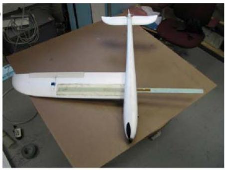
natural_image
White model airplane on a cardboard table, no visible text or symbols
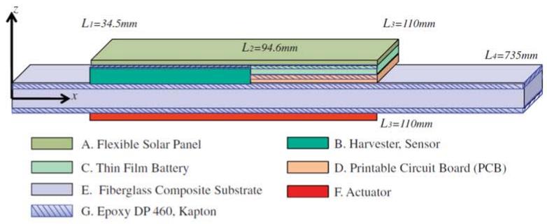
text_image
L1=34.5mm L2=94.6mm L3=110mm L4=735mm x z A. Flexible Solar Panel B. Harvester, Sensor C. Thin Film Battery D. Printable Circuit Board (PCB) E. Fiberglass Composite Substrate F. Actuator G. Epoxy DP 460, Kapton
(c)
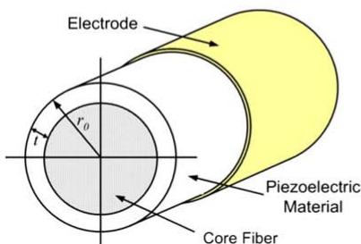
text_image
Electrode r₀ t Piezoelectric Material Core Fiber
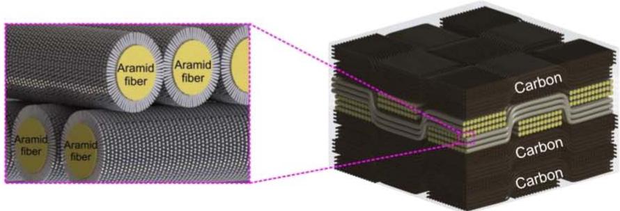
text_image
Aramid fiber Aramid fiber Aramid fiber Aramid fiber Carbon Carbon Carbon
Figure 17. Various multifunctional piezoelectric energy harvesting systems including (a) multifunctional energy harvester on UAV wing spar (reproduced with permission from [29]. © 2011 by Steven R. Anton. Published by the American Institute of Aeronautics and Astronautics, Inc., with permission), (b) self-powered gust alleviation (reproduced with permission from [447] by SAGE Publications, Ltd), (c) fiber-based multifunctional harvester (reprinted from [448], with the permission of AIP Publishing), (d) multifunctional composite (adapted from [449] with permission of The Royal Society of Chemistry).
Lin and Sodano in 2008 [450] introduced fiber-based multifunctional piezoelectric energy harvesting devices through the deposition of piezoceramics on the surface of the reinforcing fiber of a composite material, thus producing a piezoelectric structural fiber. The reinforcing fiber was selected to be conductive so as to serve as one of the electrodes, while the outside of the piezoceramic was coated with the second electrode. The fiber core provides structural properties as well as acting as an inner electrode, and the piezoelectric layer endows functionality to the fiber such that it can be used for embedded sensing, actuation, and energy harvesting in a composite material. The authors fabricated, modeled, and experimentally characterized the multifunctional fiber using a silicon carbide core coated with a layer of piezoelectric material and an outer electrode composed of silver. Single fiber composites were created by coating the fiber with a layer of epoxy with varying thickness, and measurements of the piezoelectric coupling were made using an atomic force microscope. Results of the study validated the material performance and showed that fiber reinforced polymer matrix composites with high bulk piezoelectric coupling coefficients could be obtained from the approach [451]. In 2009, Lin and Sodano [448] investigated the energy storage ability of the fibers (figure 17(c)). The dielectric properties of the active shell were studied in order to create a structural fiber capacitor. Results of experimental testing showed that fibers with a 0.23 aspect ratio exhibited an energy storage density of showing that the fibers were capable of storing harvested energy, thus demonstrating the capacity of the multifunctional fiber to both harvest and store energy.
More recently in the same research group, Malakooti et al in 2016 [449] developed a multifunctional composite using ZnO nanowires grown on the surface of Kevlar fibers, and created an energy harvester by laying up a composite with carbon fiber plies as electrodes and the ZnO coated Kevlar as a harvesting layer (figure 17(d)). The architecture was designed such that the inclusion of the ZnO nanowires lead to an increase in the composite’s tensile strength and stiffness by approximately 30%, while the composite simultaneously showed strong energy harvesting capacity due to the presence of the piezoelectric nanowires. This multifunctional approach was novel since the inclusion of the piezoelectric material enhanced both the mechanical behavior while adding functionality to the structure. The approach was adapted for the development of coated fibers by Bowland et al in 2017 [452], and Groo et al in 2018 [453] demonstrated that the same architecture could also be used for SHM analysis.
3.7. Multi-source energy harvesting
One of the challenges of conventional energy harvesting systems is the fact that they utilize a single energy conversion mechanism, thus their performance is highly linked to ambient energy levels; fluctuations in which can severely impact the performance of the system. If ambient energy levels drop below a critical value, the harvester may stop functioning. One method of addressing this challenge is to create multi-source energy harvesting systems that simultaneously harvest from multiple ambient energy sources, such that the overall system is more robust against varying ambient conditions.
In recent years, researchers have begun to investigate multi-source energy harvesting systems that combine piezoelectric vibration harvesting with other forms of energy harvesting. Magoteaux et al in 2008 [454] investigated the potential benefit of integrating solar and piezoelectric energy harvesting devices into unmanned air vehicles in order to extend the working time of the aircraft with recharging the battery. It was shown that an aircraft equipped with a monocrystalline solar cell and two piezoelectric cantilever beams on the landing gear outperforms the same aircraft without energy harvesters. Gambier et al in 2012 [455] introduced multi-source harvesting ability to the self-charging structure concept developed by Anton et al [446] through the inclusion of thin-film solar panels to the system, thus achieving simultaneous vibration and solar harvesting (figure 18(a)). Thermoelectric harvesting was also considered in this work, however, the generator was separate from the piezoelectric/solar harvester composite. Experimental results revealed that 1 mAh of energy could be charged in the thinfilm battery in 8 h using the piezoelectric harvester (base excitation of 0.5 g at 56.4 Hz), in 40 min using thermal energy (temperature difference of , and in 20 min using solar energy (solar irradiance level of 223 .
In a study performed by Schlichting and Garcia in 2013 [461], the potential of energy harvesting from solar and vibratory energy in order to power a bio-logger for bird tracking and biophysical monitoring during migration was investigated. A commercially available solar panel combined with a piezoelectric energy harvester were utilized. Combining high power density solar panels with the piezoelectric harvester makes generating power possible even in limited diurnal cycles and weather conditions without adequate sunlight. A power management system was developed to condition the lowvoltage DC power signal of the solar cells and high voltage signals generated by the piezoelectric transducer that considered the weight limits of birds. Analytical simulations showed that the system was capable of providing power for sustained, long duration functioning of a uric acid sensor. In another work [462], this group analytically explored several energy harvesting circuit designs capable of simultaneously harvesting energy from the solar and vibration energy harvesters and provided comparisons between the designs.
Anton et al in 2013 [456] presented a study in which combined piezoelectric and solar energy harvesting was applied to power a structural health monitoring sensor node on a small-scale wind turbine. Specifically, several piezoelectric harvesters and a thin-film solar panel were installed on the root of a turbine blade (figure 18(b)), and a hysteretic multi-source energy harvesting circuit was used to combine the energy from multiple harvesters to power a WID 3.0 (wireless impedance device) sensor node [463]. Experimental field testing showed that the piezoelectric harvester output was orders of magnitude less than the solar harvester output, but that the combined system could successfully simultaneously harvest solar and vibration energy and power the WID node during operation.
In an effort to increase the power generation performance of beam harvesters, Challa et al in 2009 [457] suggested a coupled piezoelectric-electromagnetic harvester. The device consisted of a piezoelectric bimorph and a permanent magnet at the tip that moves inside a coil (figure 18(c)). The electromagnetic components were added to the piezoelectric generator to increase the power through matching the total electrical damping to the mechanical damping of the system. An increase of 30% in generated power from the combined piezoelectric-electromagnetic harvester compared to the optimized, standalone piezoelectric and electromagnetic energy harvesting devices was observed. A similar design was proposed by Tadesse et al in 2009 [458], in which PZN-PT crystals were attached to a cantilever beam with a tip magnet and a stationary coil (figure 18(d)). It was demonstrated that an optimized generator prototype was able to generate 0.25 W using the electromagnetic mechanism and 0.25 mW using the piezoelectric mechanism at 35 g of acceleration at 20 Hz. Li et al in 2015 [459] proposed another hybrid piezoelectric-electromagnetic energy harvester and modeled it under random vibration excitation. The design is a double-ended piezoelectric beam with a center magnetic mass and set of coils placed under the magnet (figure 18(e)). Experimental results showed that a mean power of around could be generated by the hybrid harvester subjected to random vibration with spectral density of acceleration of . Zi et al in 2015 [460] suggested a triboelectric-pyroelectric-piezoelectric hybrid cell consisting of a sliding mode triboelectric nanogenerator (TENG), and a pyroelectric-piezoelectric (thermal-mechanical harvester) nanogenerator (figure 18(f)). The power density of the TENG alone was 0.15 W at 4.4 Hz sliding. The hybrid device uses the mechanical energy and frictioninduced heat on the TENG to double the generated power compared to the TENG alone. The multilayer harvester is composed of the sliding-mode harvester on the top and the pyroelectric-piezoelectric nanogenerator on the bottom. The total energy efficiency of the system was about 26.2%.
3.8. Other applications
This section summarizes the studies carried out on nonconventional sources reported in the literature for piezoelectric energy harvesting and presents examples of autonomous sensor nodes with embedded piezoelectric generators. Energy harvesting from acoustic energy, thermoacoustic waves, propagating acoustic waves in solids, bicycle vibration, and friction-induced vibration are examples of nonconventional energy sources studied by researchers.
Energy scavenging from acoustic waves in the form of sound is a relatively new application for piezoelectric energy harvesting devices. One of the original studies in this area was
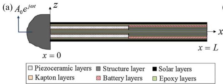
text_image
(a) A₀e^{jωt} x = 0 z x = L Piezoceramic layers Structure layer Solar layers Kapton layers Battery layers Epoxy layers
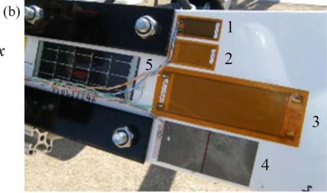
text_image
(b) 1 2 3 4 5
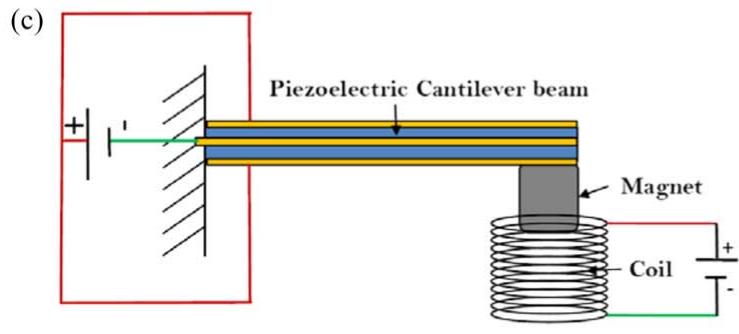
text_image
(c) Piezoelectric Cantilever beam Magnet Coil
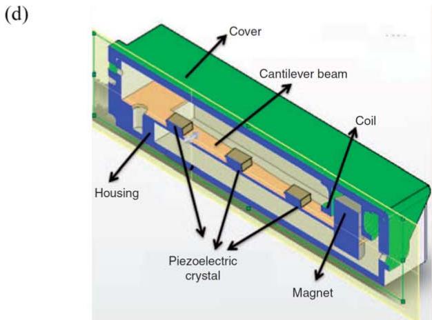
text_image
(d) Cover Cantilever beam Coil Housing Piezoelectric crystal Magnet
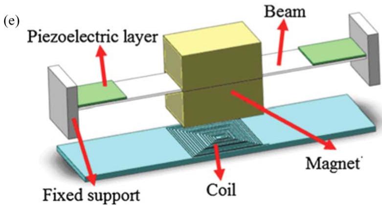
text_image
(e) Piezoelectric layer Beam Fixed support Coil Magnet
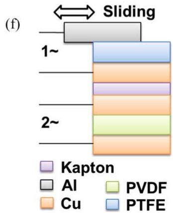
text_image
(f) Sliding 1~ 2~ Kapton Al PVDF Cu PTFE
Figure 18. Various multi-source energy harvesters including (a) piezoelectric-solar harvester (reproduced from [455]. © IOP Publishing Ltd. All rights reserved), (b) piezoelectric-solar harvester on turbine blade (copyright [456] 2013. Society of Photo Optical Instrumentation Engineers), (c) piezoelectric-electromagnetic harvester (reproduced from [457]. © IOP Publishing Ltd. All rights reserved), (d) PZN-PT piezoelectric-electromagnetic harvester (reproduced with permission from [458] by SAGE Publications, Ltd), (e) double-ended piezoelectricelectromagnetic harvester (reprinted by permission from Springer Nature: [Springer] [Microsystem technologies] [459] © 2015), and (f) triboelectric-pyroelectric-piezoelectric harvester ([460] John Wiley & Sons. © 2015 WILEY‐VCH Verlag GmbH & Co. KGaA, Weinheim).
presented by Liu et al in 2008 [464]. Using a Helmholtz resonator consisting of an orifice, a cavity, and a piezoelectric diaphragm, the energy generated from the fluctuating pressure of sound waves was harvested. It was shown that 30 mW of power can be generated for an incident sound pressure level of 160 dB. Later in 2013, Li et al [160, 161] utilized a quarter-wavelength straight tube resonator with multiple piezoelectric plates placed inside the tube to harvest energy from traveling sound at low audible frequency. An output power of 12.7 mW was obtained with an incident sound pressure of 110 dB corresponding to a power density of 15.1 . A more comprehensive review on energy harvesting from sound waves can be found in the review by Choi et al in 2019 [465].
Smoker et al in 2012 [466] presented a piezoelectric harvester architecture in order to scavenge power from standing waves generated in a thermoacoustic engine. The thermo-acoustic-piezoelectric engine consists of a heat cavity, stack, resonator tube, Helmholtz resonator cavity, and piezoelectric diaphragm. Acoustic waves amplified by the Helmholtz resonator were harnessed by the piezoelectric diaphragm placed on the outlet of the resonator. Experimental results showed that 0.128 mW of power could be generated from 44.82 W of input thermal energy with an overall conversion efficiency of 0.000 28%. Chen et al in 2019 [467] proposed another thermoacoustic piezoelectric engine design to convert the acoustic energy produced by a standing-wave thermoacoustic engine to electricity. The design removed the Helmholtz resonator and placed the piezoelectric diaphragm on the inlet of the resonator to form an open-end engine. An experimentally validated analytical model was developed to investigate the stability of the engine as well as to predict the onset temperature difference across the stack and the oscillation frequency. Using a parametric study, the effect of various electrical and geometrical parameters on onset characterization of the system was investigated. A more comprehensive review on various acoustic and thermoacoustic energy harvesting techniques is provided by Pillai and Deenadayalan [468]. Elfrink et al in 2010 [469] proposed a thinfilm MEMS energy harvester based on aluminum nitride piezoelectric material integrated in a wireless autonomous sensor node equipped with a temperature sensor. The harvester is a piezoelectric cantilever with dimensions of and a large proof mass. Experimental results showed that the device could generated 10 μW of regulated power under an excitation amplitude of 0.64 g at 353 Hz, which is sufficient to power the sensor and wireless transmitter once every 15 s over a distance of 15 m. Another self-powered sensor node was developed by Zhu et al in 2011 [470] incorporating an accelerometer, a temperature sensor, a pressure sensor, a microcontroller with RF components, a piezoelectric energy harvester, and a power storage supercapacitor in a credit card-sized package (figure 19(a)). A piezoelectric bimorph with a resonance frequency of 67 Hz showed a power output of 240 under an excitation of 0.4 g, which was enough to operate the sensor node once every 15 min.
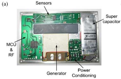
text_image
(a) Sensors Super capacitor MCU & RF Generator Power Conditioning
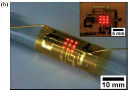
natural_image
Close-up of a cylindrical electronic component with glowing internal structures, shown with an inset schematic of a microfluidic device labeled ‘KAIST’ at 5 mm scale and 10 mm scale.
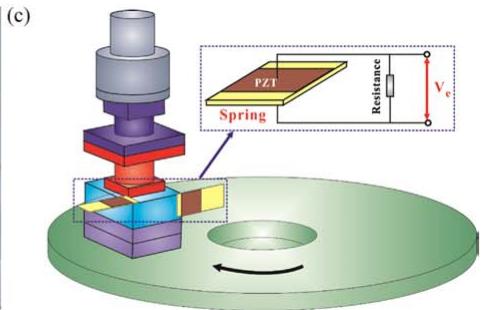
text_image
(c) PZT Spring Resistance Vc
Figure 19. Various alternative piezoelectric energy harvesters including (a) self-powered credit card-sized sensor node (reprinted from [470], Copyright 2011, with permission from Elsevier), (b) self-powered flexible light-emitting device (reproduced from [471] with permission of The Royal Society of Chemistry), and (c) frictional energy harvester (reprinted from [472], Copyright 2018, with permission from Elsevier).
In the work performed by Jeong et al in 2014 [471] a self-powered flexible light-emitting optoelectronic (flexible vertically structured AlGaInP-based LED (f-VLED)) device powered by a high-output flexible piezoelectric energy harvester was developed (figure 19(b)). The harvester was made from a flexible PZT thin film. Experimental tests showed that a high voltage of 140 V and a current of 10 could be generated through slight finger motions and it could operate an f-VLED array without any external energy supply. Use of the device in bio-implantable applications (optical biosensors, phototherapy, and optogenetics), MEMS, and mobile/wearable optoelectronics was suggested.
Vasic et al in 2014 [473] investigated the application of a cantilever piezoelectric energy harvester with tip mass for energy harvesting from bicycle vibrations. Using four accelerometers, the vibration of the bicycle at the fork, saddle, frame, and handlebars was studied. The maximum amplitude of vibration was found at the handlebar or fork (2.5 m at 18.8 Hz) and increases with bicycle speed. This vibration amplitude cannot be observed from pedaling, which has a frequency between 3 to 5 Hz. In order to optimize the conversion performance and to rectify the piezoelectric voltage, a switching-type electric interface (SSHI) was utilized. Part of the harvested energy is allocated to power the switches in the SSHI interface. Experimental results showed that the largest amplitudes of vibration were found in the frequency range between 2 to 30 Hz, so the harvester does not need a broad frequency response. A piezoelectric patch was used to detect velocity zero-crossing to drive the switches of the SSHI circuit. For a bicycle traveling at a speed of 21 km (13 mph) on pavement and with a 200 kΩ load resistor, 3.4 mW of power was obtained. The power for other speeds is low and the application of multiple piezoelectric beams or nonlinear methods was suggested.
Wang et al in 2018 [472] performed a feasibility study on energy harvesting from friction-induced vibration in brake systems, tool cutting systems, mechanical gear systems, window wiper blades, lead screw drives, etc. A PZT-5A patch with dimension of was placed between a fixed block and a rotary disc which are compressed against each other using a pre-compressed spring (figure 19(c)). Experimental and numerical results showed that relative speed and the normal load between the interacting surfaces both highly affect the dynamics of the system as well as the output of harvester. Experimental results showed that a highly fluctuating voltage output of around 1 V could be obtained under a normal load of 725 N, a rotation speed of 20 RPM, and a load resistance of 30 kΩ.
4. Concluding remarks
Piezoelectric energy harvesting has become an extremely extensive field of research during the past two decades. Although it is challenging to summarize all of the works published in this area in the past decade, this article attempts to present a concise summary of the most impactful studies published since we published our original review article in 2007 [1]. We hope that this article was able to successfully capture the recent growth of the field of piezoelectric energy harvesting, and to provide adequate acknowledgement of the many research groups pursuing this interesting research area. When combined with our original review article [1], we also hope that this article is a useful resource for both current and future researchers interested in the field of piezoelectric energy harvesting.
The continuous development of new piezoelectric materials with enhanced electromechanical, mechanical, thermal, and biocompatible properties has led to the introduction of various new piezoelectric materials including single crystals, lead-free piezoelectrics, high-temperature piezoelectrics, piezoelectret foams, and piezoelectric nanocomposites. While conventional linear, beam-based piezoelectric transducers have been widely used, the emersion of nonlinear and broadband harvesters has extended the frequency and power generation performance of piezoelectric devices. These novel materials and transducers have been extensively employed to develop application-based devices to harvest energy from fluid flow, the human body, animals, infrastructure, and vehicles. There has been a major interest in the researcher community to develop various wearable and implantable energy harvesting devices to power portable electronics as well as medical devices. Multifunctional energy harvesting technologies have also been introduced to develop integrated harvesting and energy storage capabilities into a single device. Simultaneous energy harvesting from multiple sources and using piezoelectric/electromagnetic/triboelectric/ pyroelectric hybrid generators has also been suggested in the literature.
Currently, many of the topics listed above remain in the research stage, and there is a substantial amount of ongoing research on developing enhanced energy harvesting materials and methods. Fabrication of piezoelectric nanofibers, piezoelectric thin films, and printable piezoelectric materials are being pursued by several research groups. Improving the bandwidth and generated power of harvesters by introducing nonlinearities to exploit the internal resonance of structures is still an ongoing research topic. There has been a significant shift in the state-of-the-art in human body energy harvesting from limb-mounted harvesters to woven, fabric-like harvesters and implantable devices. New technologies have allowed researchers to fabricate very flexible piezoelectric devices and electronics, which have opened new doors in developing biocompatible and durable harvesters to generate the required power for embedded medical devices. Finally, metamaterials and metastructures have emerged as a novel method to increase the coupling between ambient energy sources and piezoelectric transducers by acoustic wave manipulation.
ORCID iDs
Mohsen Safaei https://orcid.org/0000-0002-8312-3000 Henry A Sodano https://orcid.org/0000-0001-6269-1802 Steven R Anton https://orcid.org/0000-0003-2777-5458
References
[1] Anton S R and Sodano H A 2007 A review of power harvesting using piezoelectric materials (2003–2006) Smart Mater. Struct. 16 R1
[2] Sullivan J and Gaines L 2010 A review of battery life-cycle analysis: state of knowledge and critical needs ANL/ESD/ 10-7 Argonne National Laboratory (ANL) (https://doi.org/ 10.2172/1000659)
[3] Paulo J and Gaspar P 2010 Review and future trend of energy harvesting methods for portable medical devices Proc. of the World Congress on Engineering (http://www.iaeng.org/ publication/WCE2010/WCE2010_pp909-914.pdf)
[4] Mitcheson P D et al 2008 Energy harvesting from human and machine motion for wireless electronic devices Proc. IEEE 96 1457–86
[5] Kanoun Olfa 2018 Energy harvesting for wireless sensor networks (Berlin, Boston: De Gruyter Oldenbourg) (https:// www.degruyter.com/view/product/462297)
[6] Seah W K, Eu Z A and Tan H-P 2009 Wireless sensor networks powered by ambient energy harvesting (WSN-HEAP)-Survey and challenges 2009 1st International Conference on Wireless Communication, Vehicular Technology, Information Theory and Aerospace & Electronic Systems Technology (IEEE) (https://doi.org/ 10.1109/WIRELESSVITAE.2009.5172411)
[7] Shaikh F K and Zeadally S 2016 Energy harvesting in wireless sensor networks: A comprehensive review Renew. Sustain. Energy Rev. 55 1041–54
[8] Yan X et al 2010 Large, solution-processable graphene quantum dots as light absorbers for photovoltaics Nano Lett. 10 1869–73
[9] Frischmann P D, Mahata K and Würthner F 2013 Powering the future of molecular artificial photosynthesis with lightharvesting metallosupramolecular dye assemblies Chem. Soc. Rev. 42 1847–70
[10] Tiwari G, Mishra R and Solanki S 2011 Photovoltaic modules and their applications: A review on thermal modelling Appl. Energy 88 2287–304
[11] Seyedmahmoudian M et al 2018 Maximum power point tracking for photovoltaic systems under partial shading conditions using bat algorithm Sustainability 10 1347
[12] Husain A A et al 2018 A review of transparent solar photovoltaic technologies Renew. Sustain. Energy Rev. 94 779–91
[13] Ng C et al 2018 Photovoltaic performances of mono-and mixed-halide structures for perovskite solar cell: A review Renew. Sustain. Energy Rev. 90 248–74
[14] Chen Y-C et al 2018 Photovoltaic energy harvesting in indoor environments 2018 IEEE Int. Instrumentation and Measurement Technology Conf. (I2MTC) (IEEE) (https:// doi.org/10.1109/I2MTC.2018.8409628)
[15] Cuadras A, Gasulla M and Ferrari V 2010 Thermal energy harvesting through pyroelectricity Sensor Actuat. A-Phys. 158 132–9
[16] Hunter S R et al 2012 Review of pyroelectric thermal energy harvesting and new MEMs-based resonant energy conversion techniques SPIE Defense, Security, and Sensing 8377 (SPIE)
[17] Blackburn J L et al 2018 Thermoelectric materials: carbonnanotube‐based thermoelectric materials and devices (Adv. Mater. 11/2018) Adv. Mater. 30 1870072
[18] Junior O A, Maran A and Henao N 2018 A review of the development and applications of thermoelectric microgenerators for energy harvesting Renew. Sustain. Energy Rev. 91 376–93
[19] Tian R et al 2018 Wearable and flexible thermoelectrics for energy harvesting MRS Bull. 43 193–8
[20] Harne R and Wang K 2013 A review of the recent research on vibration energy harvesting via bistable systems Smart Mater. Struct. 22 023001
[21] Saadon S and Sidek O 2011 A review of vibration-based MEMS piezoelectric energy harvesters Energ. Convers. Manage. 52 500–4
[22] Stephen N 2006 On energy harvesting from ambient vibration J. Sound Vib. 293 409–25
[23] Wang H, Jasim A and Chen X 2018 Energy harvesting technologies in roadway and bridge for different applications–A comprehensive review Appl. Energy 212 1083–94
[24] Díez P L et al 2018 A comprehensive method to taxonomize mechanical energy harvesting technologies 2018 IEEE Int. Symp. on Circuits and Systems (ISCAS) (IEEE) (https://doi. org/10.1109/ISCAS.2018.8350907)
[25] Narita F and Fox M 2018 A review on piezoelectric, magnetostrictive, and magnetoelectric materials and device technologies for energy harvesting applications Adv. Eng. Mater. 20 1700743
[26] Uchino K 2018 Piezoelectric energy harvesting systems— Essentials to successful developments Energy Technol. 6 829–48
[27] Ali S F, Friswell M I and Adhikari S 2011 Analysis of energy harvesters for highway bridges J. Intell. Mater. Syst. Struct. 22 1929–38
[28] Erturk A 2011 Piezoelectric energy harvesting for civil infrastructure system applications: moving loads and surface strain fluctuations J. Intell. Mater. Syst. Struct. 22 1959–73
[29] Anton S R, Erturk A and Inman D J 2012 Multifunctional unmanned aerial vehicle wing spar for low-power generation and storage J. Aircr. 49 292–301
[30] Erturk A, Renno J M and Inman D J 2009 Modeling of piezoelectric energy harvesting from an l-shaped beam-mass structure with an application to UAVs J. Intell. Mater. Syst. Struct. 20 529–44
[31] Featherston C A, Holford K M and Greaves B 2009 Harvesting vibration energy for structural health monitoring in aircraft Key Eng. Mater. 413–414 439–46
[32] Lee S and Youn B D 2011 A new piezoelectric energy harvesting design concept: multimodal energy harvesting skin IEEE T .Ultrason. Ferr. 58 629–45
[33] Le M Q et al 2015 Review on energy harvesting for structural health monitoring in aeronautical applications Prog. Aerosp. Sci. 79 147–57
[34] Karami M A and Inman D J 2012 Powering pacemakers from heartbeat vibrations using linear and nonlinear energy harvesters Appl. Phys. Lett. 100 042901
[35] Qi Y et al 2010 Piezoelectric ribbons printed onto rubber for flexible energy conversion Nano Lett. 10 524–8
[36] Zhang Y et al 2018 Micro electrostatic energy harvester with both broad bandwidth and high normalized power density Appl. Energy 212 362–71
[37] Zhang Y et al 2016 Electrostatic energy harvesting device with dual resonant structure for wideband random vibration sources at low frequency Rev. Sci. Instrum. 87 125001
[38] Miljkovic N et al 2014 Jumping-droplet electrostatic energy harvesting Appl. Phys. Lett. 105 013111
[39] Banerji S, Bagchi A and Khazaeli S 2016 STR-991: Energy harvesting methods for structural health monitoring using
wireless sensors: A review Annual Conf. of the Canadian Society for Civil Engineering
[40] Moss S D et al 2015 Scaling and power density metrics of electromagnetic vibration energy harvesting devices Smart Mater. Struct. 24 023001
[41] Tan Y, Dong Y and Wang X 2017 Review of MEMS electromagnetic vibration energy harvester J. Microelectromech. Syst. 26 1–16
[42] Asai T, Araki Y and Ikago K 2017 Energy harvesting potential of tuned inertial mass electromagnetic transducers Mech. Syst. Sig. Process. 84 659–72
[43] Fang Z-W et al 2017 Integration of a nonlinear energy sink and a giant magnetostrictive energy harvester J. Sound Vib. 391 35–49
[44] Cao S et al 2018 Modeling and design of an efficient magnetostrictive energy harvesting system with low voltage and low power IEEE T. Magn. 54 1-5
[45] Clemente C S et al 2017 A magnetostrictive energy harvesting system for bridge structural health monitoring Advances in Science and Technology 101 (Switzerland: Trans Tech Publ.) 20-25
[46] Adly A et al 2010 Experimental tests of a magnetostrictive energy harvesting device toward its modeling J. Appl. Phys. 107 09A935
[47] Wang L and Yuan F 2008 Vibration energy harvesting by magnetostrictive material Smart Mater. Struct. 17 045009
[48] Chen J et al 2015 Networks of triboelectric nanogenerators for harvesting water wave energy: A potential approach toward blue energy ACS Nano 9 3324–31
[49] Khan U and Kim S-W 2016 Triboelectric nanogenerators for blue energy harvesting ACS Nano 10 6429–32
[50] Wang Z L 2015 Triboelectric nanogenerators as new energy technology and self-powered sensors–Principles, problems and perspectives Faraday Discuss. 176 447–58
[51] Zi Y et al 2016 Harvesting low-frequency (<5 Hz) irregular mechanical energy: a possible killer application of triboelectric nanogenerator ACS Nano 10 4797–805
[52] Xu L et al 2018 Coupled triboelectric nanogenerator networks for efficient water wave energy harvesting ACS Nano 12 1849–58
[53] Chen B, Yang Y and Wang Z L 2018 Scavenging wind energy by triboelectric nanogenerators Adv. Energy Mater. 1702649
[54] Stojčev M K, Kosanović M R and Golubović L R 2009 Power management and energy harvesting techniques for wireless sensor nodes 2009 9th Int. Conf. on Telecommunication in Modern Satellite, Cable, and Broadcasting Services (IEEE) (https://doi.org/10.1109/TELSKS.2009.5339410)
[55] Panda P 2009 Review: environmental friendly lead-free piezoelectric materials J. Mater. Sci. 44 5049–62
[56] Priya S and Nahm S 2011 Lead-Free Piezoelectrics (New York: Springer) (https://doi.org/10.1007/978-1-4419- 9598-8)
[57] Uchino K 2017 The development of piezoelectric materials and the new perspective Advanced Piezoelectric Materials 2nd edn (Amsterdam: Elsevier) p 1–92
[58] Marino A et al 2017 Piezoelectric nanotransducers: The future of neural stimulation Nano Today 14 9–12
[59] Gao X et al 2018 Giant piezoelectric coefficients in relaxor piezoelectric ceramic PNN‐PZT for vibration energy harvesting Adv. Funct. Mater. 28 1706895
[60] Damjanovic D 1998 Ferroelectric, dielectric and piezoelectric properties of ferroelectric thin films and ceramics Rep. Prog. Phys. 61 1267
[61] Messing G L et al 2004 Templated grain growth of textured piezoelectric ceramics Crit. Rev. Solid State Mater. Sci. 29 45–96
[62] Isarakorn D et al 2010 Epitaxial piezoelectric MEMS on silicon J. Micromech. Microeng. 20 055008
[63] Muralt P, Polcawich R and Trolier-McKinstry S 2009 Piezoelectric thin films for sensors, actuators, and energy harvesting MRS Bull. 34 658–64
[64] Roscow J, Taylor J and Bowen C 2016 Manufacture and characterization of porous ferroelectrics for piezoelectric energy harvesting applications Ferroelectrics 498 40–6
[65] Martínez-Ayuso G et al 2017 Homogenization of porous piezoelectric materials Int. J. Solids Struct. 113 218–29
[66] Roscow J et al 2017 Modelling and fabrication of porous sandwich layer barium titanate with improved piezoelectric energy harvesting figures of merit Acta Mater. 128 207–17
[67] Pan C-T et al 2015 Significant piezoelectric and energy harvesting enhancement of poly (vinylidene fluoride)/ polypeptide fiber composites prepared through near-field electrospinning J. Mater. Chem. A 3 6835–43
[68] Harstad S et al 2017 Enhancement of β-phase in PVDF films embedded with ferromagnetic Gd Si nanoparticles for piezoelectric energy harvesting AIP Adv. 7 056411
[69] Erturk A, Bilgen O and Inman D J 2008 Power generation and shunt damping performance of a single crystal lead magnesium niobate-lead zirconate titanate unimorph: Analysis and experiment Appl. Phys. Lett. 93 224102
[70] Palneedi H et al 2017 Strong and anisotropic magnetoelectricity in composites of magnetostrictive Ni and solid-state grown lead-free piezoelectric BZT–BCT single crystals J. Asian Ceram. Soc. 5 36–41
[71] Ko S-Y et al 2017 Improved solid-state conversion and piezoelectric properties of 90Na1/2Bi1/2TiO3-5BaTiO3-5K1/2Na1/2NbO3 single crystals J. Eur. Ceram. Soc. 37 407–11
[72] Rao G B, Rajesh P and Ramasamy P 2017 Enhanced optical, thermal and piezoelectric behavior in dye doped potassium acid phthalate (KAP) single crystal J. Cryst. Growth 468 411–5
[73] Jaffe Bernard et al 1971 Piezoelectric Ceramics (Amsterdam: Elsevier)
[74] Ren B et al 2010 Piezoelectric energy harvesting using shear mode 0.71Pb(Mg1/3Nb2/3)O3-0.29PbTiO3 single crystal cantilever Appl. Phys. Lett. 96 083502
[75] Mathers A, Moon K S and Yi J 2009 A vibration-based PMN-PT energy harvester IEEE Sens. J. 9 731–9
[76] Moon S E et al 2009 Sustainable vibration energy harvesting based on Zr-doped PMN-PT piezoelectric single crystal cantilevers ETRI J. 31 688–94
[77] Lee S-M et al 2004 Effect of lead zinc niobate addition on sintering behavior and piezoelectric properties of lead zirconate titanate ceramic J. Mater. Res. 19 2553–6
[78] Yan Y, Cho K H and Priya S 2011 Identification and effect of secondary phase in MnO2‐doped 0.8 Pb (Zr0.52Ti0.48) O –0.2 Pb (Zn1/3Nb2/3)O piezoelectric ceramics J. Am. Ceram. Soc. 94 3953–9
[79] Zheng M et al 2014 Shift of morphotropic phase boundary in high-performance fine-grained PZN–PZT ceramics J. Eur. Ceram. Soc. 34 2275–83
[80] Yue Y et al 2017 High power density in a piezoelectric energy harvesting ceramic by optimizing the sintering temperature of nanocrystalline powders J. Eur. Ceram. Soc. 37 4625–30
[81] Shahab S, Zhao S and Erturk A 2018 Soft and hard piezoelectric ceramics and single crystals for random vibration energy harvesting Energy Technol. 6 935–42
[82] Yang Z and Zu J 2016 Comparison of PZN-PT, PMN-PT single crystals and PZT ceramic for vibration energy harvesting Energ. Convers. Manage. 122 321–9
[83] Hwang G T et al 2015 A reconfigurable rectified flexible energy harvester via solid‐state single crystal grown PMN– PZT Adv. Energy Mater. 5 1500051
[84] Shibata K et al 2018 Applications of lead-free piezoelectric materials MRS Bull. 43 612–6
[85] Zheng T et al 2018 Recent development in lead-free perovskite piezoelectric bulk materials Prog. Mater. Sci. 98 552–624
[86] Zhang Y, Sun H and Chen W 2017 A brief review of Ba based lead-free piezoelectric ceramics: past, present and future perspectives J. Phys. Chem. Solids 114 207–19
[87] Leontsev S O and Eitel R E 2010 Progress in engineering high strain lead-free piezoelectric ceramics Sci. Technol. Adv. Mater. 11 044302
[88] Kang W-S and Koh J-H 2015 (1−x) Bi0.5Na0.5TiO3–xBaTiO3 lead-free piezoelectric ceramics for energy-harvesting applications J. Eur. Ceram. Soc. 35 2057–64
[89] Rödel J et al 2015 Transferring lead-free piezoelectric ceramics into application J. Eur. Ceram. Soc. 35 1659–81
[90] Maurya D et al 2018 Lead-free piezoelectric materials and composites for high power density energy harvesting J. Mater. Res. 33 1–29
[91] Wu M et al 2018 High performance piezoelectric energy harvester and self-powered mechanosensing using lead free potassium− sodium niobate flexible piezoelectric composites J. Mater. Chem. A 6 16439–49
[92] Yan X et al 2017 Composition-driven phase boundary and its energy harvesting performance of BCZT lead–free piezoelectric ceramic J. Eur. Ceram. Soc. 37 2583–9
[93] Yan X et al 2018 High energy conversion efficiency in Mnmodified Ba0.9Ca0.1Ti0.93Zr0.07O3 lead‐free energy harvester J. Am. Ceram. Soc. 101 2330–8
[94] Zheng M et al 2017 A highly dense structure boosts energy harvesting and cycling reliabilities of a high-performance lead-free energy harvester J. Mater. Chem. C 5 7862–70
[95] Zhang S et al 2009 Characterization of high temperature piezoelectric crystals with an ordered langasite structure J. Appl. Phys. 105 114107
[96] Jiang X et al 2013 High-temperature piezoelectric sensing Sensors 14 144–69
[97] Shinekumar K and Dutta S 2015 High-temperature piezoelectrics with large piezoelectric coefficients J. Electron. Mater. 44 613
[98] Qaiser M A et al 2018 0–3 type Bi3TaTiO9: 40 wt% BiFeO3 composite with improved high-temperature piezoelectric properties J. Alloys Compd. 740 1–6
[99] Li Q et al 2017 High temperature dielectric, ferroelectric and piezoelectric properties of Mn-modified BiFeO -BaTiO lead-free ceramics J. Mater. Sci. 52 229–37
[100] Tong K et al 2018 Enhanced piezoelectric response and hightemperature sensitivity by site-selected doping of BiFeO -BaTiO ceramics J. Eur. Ceram. Soc. 38 1356–66
[101] Tong K et al 2017 Enhanced piezoelectricity and hightemperature sensitivity of Zn-modified BF-BT ceramics by in situ and ex situ measuring Ceram. Int. 43 3734–40
[102] Davis M J et al 2018 Piezoelectric glass-ceramic for hightemperature applications J. Non-Cryst. Solids 501 159–66
[103] Bent A A 1997 Active fiber composites for structural actuation PhD Thesis Massachusetts Institute of Technology
[104] Wilkie W K et al 2000 Low-cost piezocomposite actuator for structural control applications SPIE’s 7th Annual International Symposium on Smart Structures and Materials 3991
[105] Klein K et al 1986 Composite piezoelectric paints Sixth IEEE Int. Symp. on Applications of Ferroelectrics (https://doi. org/10.1109/ISAF.1986.201143)
[106] Hanner K et al 1989 Thin film 0–3 polymer/piezoelectric ceramic composites: Piezoelectric paints Ferroelectrics 100 255–60
[107] Wang Z L and Song J 2006 Piezoelectric nanogenerators based on zinc oxide nanowire arrays Science 312 242–6
[108] Xu S et al 2010 Self-powered nanowire devices Nat. Nanotechnol. 5 366–73
[109] Liu J et al 2008 Carrier density and Schottky barrier on the performance of DC nanogenerator Nano Lett. 8 328–32
[110] Briscoe J et al 2012 Nanostructured p‐n junctions for kineticto‐electrical energy conversion Adv. Energy Mater. 2 1261–8
[111] Hatch S M, Briscoe J and Dunn S 2013 A Self‐Powered ZnO‐Nanorod/CuSCN UV Photodetector Exhibiting Rapid Response Adv. Mater. 25 867–71
[112] Jalali N et al 2014 Improved performance of p–n junctionbased ZnO nanogenerators through CuSCN-passivation of ZnO nanorods J. Mater. Chem. A 2 10945–51
[113] Hu Y et al 2012 Replacing a battery by a nanogenerator with 20 V output Adv. Mater. 24 110–4
[114] Sohn J I et al 2013 Engineering of efficiency limiting free carriers and an interfacial energy barrier for an enhancing piezoelectric generation Energ. Environ. Sci. 6 97–104
[115] Lee S et al 2013 Solution-processed Ag-doped ZnO nanowires grown on flexible polyester for nanogenerator applications Nanoscale 5 9609–14
[116] Kim D et al 2014 Self‐compensated insulating ZnO‐based piezoelectric nanogenerators Adv. Funct. Mater. 24 6949–55
[117] Shin S-H et al 2014 Lithium-doped zinc oxide nanowires– polymer composite for high performance flexible piezoelectric nanogenerator ACS Nano 8 10844–50
[118] Sohn J I et al 2014 A low temperature process for phosphorous doped ZnO nanorods via a combination of hydrothermal and spin-on dopant methods Nanoscale 6 2046–51
[119] Xue X et al 2013 Surface free-carrier screening effect on the output of a ZnO nanowire nanogenerator and its potential as a self-powered active gas sensor Nanotechnology 24 225501
[120] Lu M-P et al 2009 Piezoelectric nanogenerator using p-type ZnO nanowire arrays Nano Lett. 9 1223–7
[121] Feenstra J and Sodano H A 2008 Enhanced active piezoelectric 0–3 nanocomposites fabricated through electrospun nanowires J. Appl. Phys. 103 124108
[122] Andrews C, Lin Y and Sodano H 2010 The effect of particle aspect ratio on the electroelastic properties of piezoelectric nanocomposites Smart Mater. Struct. 19 025018
[123] Andrews C et al 2011 Influence of aspect ratio on effective electromechanical coupling of nanocomposites with lead zirconate titanate nanowire inclusion J. Intell. Mater. Syst. Struct. 22 1879–86
[124] Zhou Z, Tang H and Sodano H A 2014 Scalable synthesis of morphotropic phase boundary lead zirconium titanate nanowires for energy harvesting Adv. Mater. 26 7547–54
[125] Zhou Z et al 2016 Lead-free 0.5 nanowires for energy harvesting Nanoscale 8 5098–105
[126] Xu S, Hansen B J and Wang Z L 2010 Piezoelectricnanowire-enabled power source for driving wireless microelectronics Nat. Commun. 1 93
[127] Lin Y, Liu Y and Sodano H A 2009 Hydrothermal synthesis of vertically aligned lead zirconate titanate nanowire arrays Appl. Phys. Lett. 95 122901
[128] Nafari A, Bowland C C and Sodano H A 2017 Ultra-long vertically aligned lead titanate nanowire arrays for energy harvesting in extreme environments Nano Energy 31 168–73
[129] Koka A and Sodano H A 2013 High-sensitivity accelerometer composed of ultra-long vertically aligned barium titanate nanowire arrays Nat. Commun. 4 2682
[130] Koka A, Zhou Z and Sodano H A 2014 Vertically aligned BaTiO3 nanowire arrays for energy harvesting Energy. Environ. Sci. 7 288–96
[131] Koka A and Sodano H A 2014 A low‐frequency energy harvester from ultralong, vertically aligned BaTiO nanowire arrays Adv. Energy Mater. 4 1301660
[132] Chang J et al 2012 Piezoelectric nanofibers for energy scavenging applications Nano Energy 1 356–71
[133] Espinosa H D, Bernal R A and Minary‐Jolandan M 2012 A review of mechanical and electromechanical properties of piezoelectric nanowires Adv. Mater. 24 4656–75
[134] Briscoe J and Dunn S 2015 Piezoelectric nanogenerators – a review of nanostructured piezoelectric energy harvesters Nano Energy 14 15–29
[135] Challagulla K and Venkatesh T 2012 Electromechanical response of piezoelectric foams Acta Mater. 60 2111–27
[136] Savolainen A and Kirjavainen K 1989 Electrothermomechanical film. Part I. Design and characteristics J. Macromol. Sci. A 26 583–91
[137] Anton S R, Farinholt K M and Erturk A 2014 Piezoelectret foam–based vibration energy harvesting J. Intell. Mater. Syst. Struct. 25 1681–92
[138] Pondrom P et al 2014 Vibration-based energy harvesting with stacked piezoelectrets Appl. Phys. Lett. 104 172901
[139] Sessler G, Pondrom P and Zhang X 2016 Stacked and folded piezoelectrets for vibration-based energy harvesting Phase Transit. 89 667–77
[140] Ray C A and Anton S R 2015 Evaluation of piezoelectret foam in a multilayer stack configuration for low-level vibration energy harvesting applications SPIE Smart Structures and Materials + Nondestructive Evaluation and Health Monitoring 9431 (SPIE) 943111
[141] Tefft E C IV 2018 A Coupled Electromechanical Model of Piezoelectret Foam in a Multi-layer Stack Configuration Tennessee Technological University
[142] Mohebbi A et al 2017 Polymer ferroelectret based on polypropylene foam: piezoelectric properties prediction using dynamic mechanical analysis Polym. Adv. Technol. 28 476–83
[143] Zhang X et al 2018 Ferroelectret nanogenerator with large transverse piezoelectric activity Nano Energy 50 52–61
[144] Mohebbi A et al 2018 Cellular polymer ferroelectret: a review on their development and their piezoelectric properties Adv. Polym. Tech. 37 468–83
[145] Erturk A and Inman D J 2008 A distributed parameter electromechanical model for cantilevered piezoelectric energy harvesters J. Vib. Acoust. 130 041002
[146] Erturk A and Inman D J 2008 On mechanical modeling of cantilevered piezoelectric vibration energy harvesters J. Intell. Mater. Syst. Struct. 19 1311–25
[147] Erturk A and Inman D J 2009 An experimentally validated bimorph cantilever model for piezoelectric energy harvesting from base excitations Smart Mater. Struct. 18 025009
[148] Goldschmidtboeing F and Woias P 2008 Characterization of different beam shapes for piezoelectric energy harvesting J. Micromech. Microeng. 18 104013
[149] Muthalif A G and Nordin N D 2015 Optimal piezoelectric beam shape for single and broadband vibration energy harvesting: modeling, simulation and experimental results Mech. Syst. Sig. Process. 54 417–26
[150] Roundy S et al 2005 Improving power output for vibrationbased energy scavengers IEEE Pervas. Comput. 4 28–36
[151] Aladwani A et al 2012 Cantilevered piezoelectric energy harvester with a dynamic magnifier J. Vib. Acoust. 134 031004
[152] Park J C and Park J Y 2013 Asymmetric PZT bimorph cantilever for multi-dimensional ambient vibration harvesting Ceram. Int. 39 S653–7
[153] Chen Z et al 2013 Broadband characteristics of vibration energy harvesting using one-dimensional phononic piezoelectric cantilever beams Physica B 410 5–12
[154] Hashimoto S et al 2013 Multi-mode and multi-axis vibration power generation effective for vehicles 2013 IEEE
International Symposium on Industrial Electronics (IEEE) (https://doi.org/10.1109/ISIE.2013.6563689)
[155] Xu J W et al 2012 Optimization of a right-angle piezoelectric cantilever using auxiliary beams with different stiffness levels for vibration energy harvesting Smart Mater. Struct. 21 065017
[156] Wu H et al 2013 A novel two-degrees-of-freedom piezoelectric energy harvester J. Intell. Mater. Syst. Struct. 24 357–68
[157] Ferrari M et al 2008 Piezoelectric multifrequency energy converter for power harvesting in autonomous microsystems Sensor. Actuat., A-Phys. 142 329–35
[158] Khameneifar F, Arzanpour S and Moallem M 2013 A piezoelectric energy harvester for rotary motion applications: design and experiments IEEE-ASME T. Mech. 18 1527–34
[159] Pozzi M 2016 Magnetic plucking of piezoelectric bimorphs for a wearable energy harvester Smart Mater. Struct. 25 045008
[160] Li B, You J H and Kim Y-J 2013 Low frequency acoustic energy harvesting using PZT piezoelectric plates in a straight tube resonator Smart Mater. Struct. 22 055013
[161] Li B et al 2013 Harvesting low-frequency acoustic energy using quarter-wavelength straight-tube acoustic resonator Appl. Acoust. 74 1271–8
[162] De Paula A S, Inman D J and Savi M A 2015 Energy harvesting in a nonlinear piezomagnetoelastic beam subjected to random excitation Mech. Syst. Sig. Process. 54 405–16
[163] Fan K et al 2015 Design and development of a multipurpose piezoelectric energy harvester Energ. Convers. Manage. 96 430–9
[164] Pillatsch P et al 2017 Degradation of bimorph piezoelectric bending beams in energy harvesting applications Smart Mater. Struct. 26 035046
[165] Lee D-G et al 2007 Novel micro vibration energy harvesting device using frequency up conversion TRANSDUCERS 2007 - 2007 International Solid-State Sensors, Actuators and Microsystems Conference (IEEE) (https://doi.org/ 10.1109/SENSOR.2007.4300269)
[166] Jung S-M and Yun K-S 2010 Energy-harvesting device with mechanical frequency-up conversion mechanism for increased power efficiency and wideband operation Appl. Phys. Lett. 96 111906
[167] Halim M A and Park J Y 2014 Theoretical modeling and analysis of mechanical impact driven and frequency upconverted piezoelectric energy harvester for low-frequency and wide-bandwidth operation Sensor. Actuat., A-Phys. 208 56–65
[168] Galchev T, Aktakka E E and Najafi K 2012 A piezoelectric parametric frequency increased generator for harvesting lowfrequency vibrations J. Microelectromech. Syst. 21 1311–20
[169] Renaud M et al 2009 Harvesting energy from the motion of human limbs: the design and analysis of an impact-based piezoelectric generator Smart Mater. Struct. 18 035001
[170] Gu L and Livermore C 2011 Impact-driven, frequency upconverting coupled vibration energy harvesting device for low frequency operation Smart Mater. Struct. 20 045004
[171] Gu L 2011 Low-frequency piezoelectric energy harvesting prototype suitable for the MEMS implementation Microelectron. J. 42 277–82
[172] Dhakar L et al 2013 A new energy harvester design for high power output at low frequencies Sensor. Actuat., A-Phys. 199 344–52
[173] Karami M A and Inman D J 2012 Parametric study of zigzag microstructure for vibrational energy harvesting J. Microelectromech. Syst. 21 145–60
[174] Sharpes N, Abdelkefi A and Priya S 2014 Comparative analysis of one-dimensional and two-dimensional cantilever
piezoelectric energy harvesters Energy Harvesting and Systems 1 209–16
[175] Shindo Y and Narita F 2014 Dynamic bending/torsion and output power of S-shaped piezoelectric energy harvesters Int. J. Mech. Mater. Des. 10 305–11
[176] Aridogan U, Basdogan I and Erturk A 2014 Analytical modeling and experimental validation of a structurally integrated piezoelectric energy harvester on a thin plate Smart Mater. Struct. 23 045039
[177] Chen X-R et al 2012 Vibration energy harvesting with a clamped piezoelectric circular diaphragm Ceram. Int. 38 S271–4
[178] Deterre M, Lefeuvre E and Dufour-Gergam E 2012 An active piezoelectric energy extraction method for pressure energy harvesting Smart Mater. Struct. 21 085004
[179] Wang W et al 2012 Vibration energy harvesting using a piezoelectric circular diaphragm array IEEE T. Ultrason. Ferr. 59 2022–26
[180] Palosaari J et al 2012 Energy harvesting with a cymbal type piezoelectric transducer from low frequency compression J. Electroceram. 28 214–9
[181] Mo C et al 2013 Modeling and experimental validation of unimorph piezoelectric cymbal design in energy harvesting J. Intell. Mater. Syst. Struct. 24 828–36
[182] Liu H et al 2012 A new S-shaped MEMS PZT cantilever for energy harvesting from low frequency vibrations below 30 Hz Microsyst. Technol. 18 497–506
[183] Aktakka E E and Najafi K 2015 Three-axis piezoelectric vibration energy harvester 2015 28th IEEE International Conference on Micro Electro Mechanical Systems (MEMS) (IEEE) (https://doi.org/10.1109/MEMSYS.2015.7051166)
[184] Xie X, Wang Q and Wu N 2014 A ring piezoelectric energy harvester excited by magnetic forces Int. J. Eng. Sci. 77 71–8
[185] Syta A et al 2015 Experimental analysis of the dynamical response of energy harvesting devices based on bistable laminated plates Meccanica 50 1961–70
[186] Yang B and Yun K-S 2012 Piezoelectric shell structures as wearable energy harvesters for effective power generation at low-frequency movement Sensor. Actuat., A-Phys. 188 427–33
[187] Soin N et al 2014 Novel ‘3D spacer’ all fibre piezoelectric textiles for energy harvesting applications Energ. Environ. Sci. 7 1670–9
[188] Bilgen O, Wang Y and Inman D J 2012 Electromechanical comparison of cantilevered beams with multifunctional piezoceramic devices Mech. Syst. Sig. Process. 27 763–77
[189] Xu T-B et al 2013 Energy harvesting using a PZT ceramic multilayer stack Smart Mater. Struct. 22 065015
[190] Safaei M, Meneghini R M and Anton S R 2017 Parametric analysis of electromechanical and fatigue performance of total knee replacement bearing with embedded piezoelectric transducers Smart Mater. Struct. 26 094002
[191] Safaei M, Meneghini R M and Anton S R 2018 Energy harvesting and sensing with embedded piezoelectric ceramics in knee implants IEEE-ASME T. Mech. 32 864–74
[192] Leland E S and Wright P K 2006 Resonance tuning of piezoelectric vibration energy scavenging generators using compressive axial preload Smart Mater. Struct. 15 1413
[193] Hu Y, Xue H and Hu H 2007 A piezoelectric power harvester with adjustable frequency through axial preloads Smart Mater. Struct. 16 1961
[194] Challa V R et al 2008 A vibration energy harvesting device with bidirectional resonance frequency tunability Smart Mater. Struct. 17 015035
[195] Li S et al 2016 Bi-resonant structure with piezoelectric PVDF films for energy harvesting from random vibration sources at low frequency Sensor. Actuat., A-Phys. 247 547–54
[196] Zhao L, Conlon S C and Semperlotti F 2015 An experimental study of vibration based energy harvesting in dynamically
tailored structures with embedded acoustic black holes Smart Mater. Struct. 24 065039
[197] Stanton S C, McGehee C C and Mann B P 2009 Reversible hysteresis for broadband magnetopiezoelastic energy harvesting Appl. Phys. Lett. 95 174103
[198] Stanton S C, McGehee C C and Mann B P 2010 Nonlinear dynamics for broadband energy harvesting: Investigation of a bistable piezoelectric inertial generator Physica D 239 640–53
[199] Zhou S et al 2014 Broadband tristable energy harvester: modeling and experiment verification Appl. Energy 133 33–9
[200] Arrieta A et al 2010 A piezoelectric bistable plate for nonlinear broadband energy harvesting Appl. Phys. Lett. 97 104102
[201] Zhou S et al 2015 Modeling and experimental verification of doubly nonlinear magnet-coupled piezoelectric energy harvesting from ambient vibration Smart Mater. Struct. 24 055008
[202] Liu W et al 2013 Novel piezoelectric bistable oscillator architecture for wideband vibration energy harvesting Smart Mater. Struct. 22 035013
[203] Cao D, Leadenham S and Erturk A 2015 Internal resonance for nonlinear vibration energy harvesting Eur. Phys. J.-Spec. Top. 224 2867–80
[204] Lallart M, Anton S R and Inman D J 2010 Frequency selftuning scheme for broadband vibration energy harvesting J. Intell. Mater. Syst. Struct. 21 897–906
[205] Zhao L, Conlon S C and Semperlotti F 2014 Broadband energy harvesting using acoustic black hole structural tailoring Smart Mater. Struct. 23 065021
[206] Quinn D D et al 2011 Comparing linear and essentially nonlinear vibration-based energy harvesting J. Vib. Acoust. 133 011001
[207] Naseer R et al 2017 Piezomagnetoelastic energy harvesting from vortex-induced vibrations using monostable characteristics Appl. Energy 203 142–53
[208] Fan K et al 2018 A monostable piezoelectric energy harvester for broadband low-level excitations Appl. Phys. Lett. 112 123901
[209] Lan C, Tang L and Qin W 2017 Obtaining high-energy responses of nonlinear piezoelectric energy harvester by voltage impulse perturbations Eur. Phys. J. Appl. Phys. 79 20902
[210] Wang W et al 2018 Comparison of harmonic balance and multi-scale method in characterizing the response of monostable energy harvesters Mech. Syst. Sig. Process. 108 252–61
[211] Wang G et al 2018 Dynamic and energetic characteristics of a bistable piezoelectric vibration energy harvester with an elastic magnifier Mech. Syst. Sig. Process. 105 427–46
[212] Zhao D et al 2018 Analysis of broadband characteristics of two degree of freedom bistable piezoelectric energy harvester Mater. Res. Express 5 085704
[213] Dasgupta S S, Rajamohan V and Jha A K 2018 Dynamic characterization of a bistable energy harvester under gaussian white noise for larger time constant Arab. J. Sci. Eng. 44 721–30
[214] Yan B, Zhou S and Litak G 2018 Nonlinear analysis of the tristable energy harvester with a resonant circuit for performance enhancement Int. J. Bifurcat. Chaos 28 1850092
[215] Zhou S et al 2018 Numerical analysis and experimental verification of broadband tristable energy harvesters tm -Technisches Messen 85 521–32
[216] Zhou Z, Qin W and Zhu P 2018 Harvesting performance of quad-stable piezoelectric energy harvester: modeling and experiment Mech. Syst. Sig. Process. 110 260–72
[217] Cottone F, Vocca H and Gammaitoni L 2009 Nonlinear energy harvesting Phys. Rev. Lett. 102 080601
[218] Erturk A, Hoffmann J and Inman D J 2009 A piezomagnetoelastic structure for broadband vibration energy harvesting Appl. Phys. Lett. 94 254102 (3 pp)
[219] Zhou S et al 2013 Enhanced broadband piezoelectric energy harvesting using rotatable magnets Appl. Phys. Lett. 102 173901
[220] Jung J et al 2015 Nonlinear dynamic and energetic characteristics of piezoelectric energy harvester with two rotatable external magnets Int. J. Mech. Sci. 92 206–22
[221] Huguet T et al 2018 Drastic bandwidth enhancement of bistable energy harvesters: study of subharmonic behaviors and their stability robustness Appl. Energy 226 607–17
[222] Cao J et al 2015 Nonlinear time-varying potential bistable energy harvesting from human motion Appl. Phys. Lett. 107 143904
[223] Harris P et al 2017 Output response identification in a multistable system for piezoelectric energy harvesting Eur. Phys. J. B 90 20
[224] Wang W et al 2017 Optimum resistance analysis and experimental verification of nonlinear piezoelectric energy harvesting from human motions Energy 118 221–30
[225] Zhou S et al 2014 Exploitation of a tristable nonlinear oscillator for improving broadband vibration energy harvesting Eur. Phys. J.-Appl. Phys. 67 30902
[226] Tehrani M G and Elliott S J 2014 Extending the dynamic range of an energy harvester using nonlinear damping J. Sound Vib. 333 623–9
[227] Mann B and Owens B 2010 Investigations of a nonlinear energy harvester with a bistable potential well J. Sound Vib. 329 1215–26
[228] Erturk A and Inman D 2011 Broadband piezoelectric power generation on high-energy orbits of the bistable Duffing oscillator with electromechanical coupling J. Sound Vib. 330 2339–53
[229] Tang Q, Yang Y and Li X 2011 Bi-stable frequency upconversion piezoelectric energy harvester driven by noncontact magnetic repulsion Smart Mater. Struct. 20 125011
[230] Leadenham S and Erturk A 2014 M-shaped asymmetric nonlinear oscillator for broadband vibration energy harvesting: harmonic balance analysis and experimental validation J. Sound Vib. 333 6209–23
[231] Leadenham S and Erturk A 2015 Nonlinear M-shaped broadband piezoelectric energy harvester for very low base accelerations: primary and secondary resonances Smart Mater. Struct. 24 055021
[232] Chen L-Q et al 2016 A broadband internally resonant vibratory energy harvester J. Vib. Acoust. 138 061007
[233] Liu D et al 2018 Piezoelectric energy harvesting using L-shaped structures J. Intell. Mater. Syst. Struct. 29 1206–15
[234] Xiong L, Tang L and Mace B R 2018 A comprehensive study of 2: 1 internal-resonance-based piezoelectric vibration energy harvesting Nonlinear Dyn. 91 1817–34
[235] Harne R, Sun A and Wang K 2016 Leveraging nonlinear saturation-based phenomena in an L-shaped vibration energy harvesting system J. Sound Vib. 363 517–31
[236] Wu Y et al 2018 An internal resonance based frequency upconverting energy harvester J. Intell. Mater. Syst. Struct. 29 2766–81
[237] Yang W and Towfighian S 2019 A parametric resonator with low threshold excitation for vibration energy harvesting J. Sound Vib. 446 129–43
[238] Sun S and Tse P W 2018 Modeling of a horizontal asymmetric U-shaped vibration-based piezoelectric energy harvester (U-VPEH) Mech. Syst. Sig. Process. 114 467–85
[239] Ahn J H et al 2018 Nonlinear piezoelectric energy harvester with ball tip mass Sensor. Actuat., A-Phys. 277 124–33
[240] Zhang Y, Tang L and Liu K 2017 Piezoelectric energy harvesting with a nonlinear energy sink J. Intell. Mater. Syst. Struct. 28 307–22
[241] Xiong L et al 2018 Broadband piezoelectric vibration energy harvesting using a nonlinear energy sink J. Phys. D: Appl. Phys. 51 185502
[242] Lu Q et al 2018 An E-shape broadband piezoelectric energy harvester induced by magnets J. Intell. Mater. Syst. Struct. 29 2477–91
[243] Daqaq M F et al 2014 On the role of nonlinearities in vibratory energy harvesting: A critical review and discussion Appl. Mech. Rev. 66 040801
[244] Jeon Y B et al 2005 MEMS power generator with transverse mode thin film PZT Sensor. Actuat., A-Phys. 122 16–22
[245] Fang H-B et al 2006 Fabrication and performance of MEMSbased piezoelectric power generator for vibration energy harvesting Microelectron. J. 37 1280–4
[246] Liu J-Q et al 2008 A MEMS-based piezoelectric power generator array for vibration energy harvesting Microelectron. J. 39 802–6
[247] Shen D et al 2009 Micromachined PZT cantilever based on SOI structure for low frequency vibration energy harvesting Sensor. Actuat., A-Phys. 154 103–8
[248] Lee B S et al 2009 Piezoelectric MEMS generators fabricated with an aerosol deposition PZT thin film J. Micromech. Microeng. 19 065014
[249] Karami M A and Inman D J 2011 Analytical modeling and experimental verification of the vibrations of the zigzag microstructure for energy harvesting J. Vib. Acoust. 133 011002
[250] Berdy D F et al 2012 Low-frequency meandering piezoelectric vibration energy harvester IEEE T. Ultrason. Ferr. 59 846–58
[251] Marzencki M, Ammar Y and Basrour S 2008 Integrated power harvesting system including a MEMS generator and a power management circuit Sensor. Actuat., A-Phys. 145–146 363–70
[252] Rezaeisaray M et al 2015 Low frequency piezoelectric energy harvesting at multi vibration mode shapes Sensor. Actuat., A-Phys. 228 104–11
[253] Wang Z et al 2017 Self-powered viscosity and pressure sensing in microfluidic systems based on the piezoelectric energy harvesting of flowing droplets ACS Appl. Mater. Inter. 9 28586–95
[254] Tian Y et al 2018 A low-frequency MEMS piezoelectric energy harvester with a rectangular hole based on bulk PZT film J. Phys. Chem. Solids 117 21–7
[255] Won S S et al 2019 Flexible vibrational energy harvesting devices using strain-engineered perovskite piezoelectric thin films Nano Energy 55 182–92
[256] Yu H et al 2014 A vibration-based MEMS piezoelectric energy harvester and power conditioning circuit Sensors 14 3323–41
[257] Aktakka E E, Peterson R L and Najafi K 2013 Wafer-level integration of high-quality bulk piezoelectric ceramics on silicon IEEE T. Electron Dev. 60 2022–30
[258] Aktakka E E, Peterson R L and Najafi K 2010 A CMOScompatible piezoelectric vibration energy scavenger based on the integration of bulk PZT films on silicon 2010 International Electron Devices Meeting (IEEE) (https://doi. org/10.1109/IEDM.2010.5703459)
[259] Tang G et al 2014 Development of high performance piezoelectric d33 mode MEMS vibration energy harvester based on PMN-PT single crystal thick film Sensor. Actuat., A-Phys. 205 150–5
[260] Yi Z et al 2017 High performance bimorph piezoelectric MEMS harvester via bulk PZT thick films on thin berylliumbronze substrate Appl. Phys. Lett. 111 013902
[261] Kuo C-L, Lin S-C and Wu W-J 2016 Fabrication and performance evaluation of a metal-based bimorph piezoelectric MEMS generator for vibration energy harvesting Smart Mater. Struct. 25 105016
[262] Jackson N et al 2017 Shock-induced aluminum nitride based MEMS energy harvester to power a leadless pacemaker Sensor. Actuat., A-Phys. 264 212–8
[263] Priya S et al 2017 A review on piezoelectric energy harvesting: Materials, methods, and circuits Energy Harvesting and Systems 4 3–39
[264] Tian W et al 2018 A review of MEMS scale piezoelectric energy harvester Appl. Sci. 8 645
[265] Kottapalli A G P et al 2019 Self-Powered and Soft Polymer MEMS/NEMS Devices (Berlin: Springer)
[266] Chen Z et al 2014 Metamaterials-based enhanced energy harvesting: A review Physica B 438 1–8
[267] Vasseur J et al 2008 Absolute forbidden bands and waveguiding in two-dimensional phononic crystal plates Phys. Rev. B 77 085415
[268] Fok L, Ambati M and Zhang X 2008 Acoustic metamaterials MRS Bull. 33 931–4
[269] Gonella S, To A C and Liu W K 2009 Interplay between phononic bandgaps and piezoelectric microstructures for energy harvesting J. Mech. Phys. Solids 57 621–33
[270] Wu L-Y, Chen L-W and Liu C-M 2009 Acoustic energy harvesting using resonant cavity of a sonic crystal Appl. Phys. Lett. 95 013506
[271] Carrara M et al 2012 Dramatic enhancement of structureborne wave energy harvesting using an elliptical acoustic mirror Appl. Phys. Lett. 100 204105
[272] Carrara M et al 2013 Metamaterial-inspired structures and concepts for elastoacoustic wave energy harvesting Smart Mater. Struct. 22 065004
[273] Tol S, Degertekin F and Erturk A 2017 Structurally embedded reflectors and mirrors for elastic wave focusing and energy harvesting J. Appl. Phys. 122 164503
[274] Tol S, Degertekin F and Erturk A 2017 Phononic crystal Luneburg lens for omnidirectional elastic wave focusing and energy harvesting Appl. Phys. Lett. 111 013503
[275] Qi S et al 2016 Acoustic energy harvesting based on a planar acoustic metamaterial Appl. Phys. Lett. 108 263501
[276] Li J et al 2016 Acoustic metamaterials capable of both sound insulation and energy harvesting Smart Mater. Struct. 25 045013
[277] Sugino C and Erturk A 2018 Analysis of multifunctional piezoelectric metastructures for low-frequency bandgap formation and energy harvesting J. Phys. D: Appl. Phys. 51 215103
[278] Hu G et al 2017 Metastructure with piezoelectric element for simultaneous vibration suppression and energy harvesting J. Vib. Acoust. 139 011012
[279] duToit N E, Wardle B L and Kim S-G 2005 Design considerations For MEMS-scale piezoelectric mechanical vibration energy harvesters Integr. Ferroelectr. 71 121–60
[280] Roundy S J and Wright P K 2004 A piezoelectric vibration based generator for wireless electronics Smart Mater. Struct. 13 1131–42
[281] duToit N E and Wardle B L 2007 Experimental verification of models for microfabricated piezoelectric vibration energy harvesters AIAA J. 45 1126–37
[282] Sodano H A, Park G and Inman D J 2004 Estimation of electric charge output for piezoelectric energy harvesting Strain 40 49–58
[283] Ajitsaria J et al 2007 Modeling and analysis of a bimorph piezoelectric cantilever beam for voltage generation Smart Mater. Struct. 16 447–54
[284] Chen S-N, Wang G-J and Chien M-C 2006 Analytical modeling of piezoelectric vibration-induced micro power generator Mechatronics 16 379–87
[285] Lu F, Lee H P and Lim S P 2004 Modeling and analysis of micro piezoelectric power generators for microelectromechanical-systems applications Smart Mater. Struct. 13 57–63
[286] Erturk A and Inman D J 2008 Issues in mathematical modeling of piezoelectric energy harvesters Smart Mater. Struct. 17 065016
[287] Elvin N G and Elvin A A 2009 A general equivalent circuit model for piezoelectric generators J. Intell. Mater. Syst. Struct. 20 3–9
[288] Erturk A 2012 Assumed-modes formulation of piezoelectric energy harvesters: euler-bernoulli, rayleigh and timoshenko models with axial deformations Comput. Struct. 106-107 214-27
[289] Anton S R, Erturk A and Inman D J 2009 Piezoelectric energy harvesting from multifunctional wing spars for UAVs—Part 2: Experiments and storage applications SPIE Smart Structures and Materials + Nondestructive Evaluation and Health Monitoring 7288 (SPIE) 72880D
[290] Tabesh A and Frechette L G 2010 A low-power stand-alone adaptive circuit for harvesting energy from a piezoelectric micropower generator IEEE T. Ind. Electron. 57 840–9
[291] Lefeuvre E et al 2007 Buck-boost converter for sensorless power optimization of piezoelectric energy harvester IEEE T. Power Electron. 22 2018–25
[292] Lefeuvre E et al 2005 Piezoelectric energy harvesting device optimization by synchronous electric charge extraction J. Intell. Mater. Syst. Struct. 16 865–76
[293] Badel A et al 2005 Efficiency enhancement of a piezoelectric energy harvesting device in pulsed operation by synchronous charge inversion J. Intell. Mater. Syst. Struct. 16 889–901
[294] Guyomar D et al 2005 Toward energy harvesting using active materials and conversion improvement by nonlinear processing IEEE T .Ultrason. Ferr. 52 584–95
[295] Lefeuvre E et al 2006 A comparison between several vibration-powered piezoelectric generators for standalone systems Sensor. Actuat, A-Phys. 126 405–16
[296] Lallart M et al 2008 Double synchronized switch harvesting (DSSH): a new energy harvesting scheme for efficient energy extraction IEEE T .Ultrason. Ferr. 55 2119–30
[297] Shen H et al 2010 Enhanced synchronized switch harvesting: A new energy harvesting scheme for efficient energy extraction Smart Mater. Struct. 19 115017
[298] Garbuio L et al 2009 Mechanical energy harvester with ultralow threshold rectification based on SSHI nonlinear technique IEEE T. Ind. Electron. 56 1048–56
[299] Lallart M et al 2011 High efficiency, wide load bandwidth piezoelectric energy scavenging by a hybrid nonlinear approach Sens. Actuat., A-Phys. 165 294–302
[300] Liang J and Liao W-H 2012 Improved design and analysis of self-powered synchronized switch interface circuit for piezoelectric energy harvesting systems IEEE T. Ind. Electron. 59 1950–60
[301] Chao P C 2011 Energy harvesting electronics for vibratory devices in self-powered sensors IEEE Sens. J. 11 3106–21
[302] Jackson H W 1959 Introduction to Electric Circuits (Englewood Cliffs, New Jersey: Prentice-Hall)
[303] Kong N et al 2010 Resistive impedance matching circuit for piezoelectric energy harvesting J. Intell. Mater. Syst. Struct. 21 1293–302
[304] Kim H et al 2007 Consideration of impedance matching techniques for efficient piezoelectric energy harvesting IEEE T. Ultrason. Ferr. 54 1851–9
[305] Badel A and Lefeuvre E 2016 Nonlinear conditioning circuits for piezoelectric energy harvesters Nonlinearity in Energy Harvesting Systems (Berlin: Springer) 321–59
[306] Brenes A, Lefeuvre E and Yoo C-S 2018 Experimental validation of wideband piezoelectric energy harvesting
based on frequency-tuning synchronized charge extraction J. Phys.: Conf. Ser. 1052 012050
[307] Brenes A et al 2018 Unipolar synchronized electric charge extraction for piezoelectric energy harvesting Smart Mater. Struct. 27 075054
[308] Brenes A et al 2018 Shunt-diode rectifier: a new scheme for efficient piezoelectric energy harvesting Smart Mater. Struct. 28 015015
[309] Liang J, Zhao Y and Zhao K 2019 Synchronized triple biasflip interface circuit for piezoelectric energy harvesting enhancement IEEE T. Power Electr. 34 275–86
[310] Guyomar D and Lallart M 2011 Recent progress in piezoelectric conversion and energy harvesting using nonlinear electronic interfaces and issues in small scale implementation Micromachines 2 274–94
[311] Szarka G D, Stark B H and Burrow S G 2012 Review of power conditioning for kinetic energy harvesting systems IEEE T. Power Electr. 27 803–15
[312] Chen B 2019 Introduction to energy harvesting transducers and their power conditioning circuits Low-Power Analog Techniques, Sensors for Mobile Devices, and Energy Efficient Amplifiers (Berlin: Springer) 3–12
[313] Abrol S and Chhabra D 2017 Harvesting piezoelectricity using different structures by utilizing fluid flow interactions Int. J. R&D Eng. Sci. Manag. 5 24–36
[314] Yang Y et al 2014 Rotational piezoelectric wind energy harvesting using impact-induced resonance Appl. Phys. Lett. 105 053901
[315] Kishore R A, Vučković D and Priya S 2014 Ultra-low wind speed piezoelectric windmill Ferroelectrics 460 98–107
[316] Priya S 2005 Modeling of electric energy harvesting using piezoelectric windmill Appl. Phys. Lett. 87 184101
[317] Priya S et al 2005 Piezoelectric windmill: A novel solution to remote sensing Japan. J. Appl. Phys. 44 L104–7
[318] Myers R, Vickers M and Kim H 2007 Small scale windmill Appl. Phys. Lett. 90 054106
[319] Tien C M T and Goo N S 2010 Use of a piezo-composite generating element for harvesting wind energy in an urban region Aircr. Eng. Aerosp. Technol. 82 376–81
[320] Bressers S et al 2011 Contact-less wind turbine utilizing piezoelectric bimorphs with magnetic actuation Structural Dynamics, Volume 3 (New York, NY: Springer) 233–43
[321] Karami M A, Farmer J R and Inman D J 2013 Parametrically excited nonlinear piezoelectric compact wind turbine Renew. Energ. 50 977–87
[322] Rezaei-Hosseinabadi N et al 2015 An efficient piezoelectric windmill topology for energy harvesting from low-speed air flows IEEE T. Ind. Electron. 62 3576–83
[323] Zhang J et al 2017 A rotational piezoelectric energy harvester for efficient wind energy harvesting Sens. Actuat., A-Phys. 262 123–9
[324] Biccario G, De Vittorio M and D’Amico S 2017 Fluids energy harvesting system with low cut-in velocity piezoelectric MEMS 2017 IEEE International Conference on IC Design and Technology (ICICDT) (IEEE) (https:// doi.org/10.1109/ICICDT.2017.7993506)
[325] Gao X, Shih W-H and Shih W Y 2013 Flow energy harvesting using piezoelectric cantilevers with cylindrical extension IEEE T. Ind. Electron. 60 1116–8
[326] Tan Y K and Panda S K 2007 A novel piezoelectric based wind energy harvester for low-power autonomous wind speed sensor IECON 2007 - 33rd Annual Conference of the IEEE Industrial Electronics Society (IEEE) (https://doi. org/10.1109/IECON.2007.4460120)
[327] Li S and Lipson H 2009 Vertical-stalk flapping-leaf generator for wind energy harvesting ASME 2009 Conf. on Smart Materials, Adaptive Structures and Intelligent Systems (ASME) 611-619
[328] Li S, Yuan J and Lipson H 2011 Ambient wind energy harvesting using cross-flow fluttering J. Appl. Phys. 109 026104
[329] Bryant M and Garcia E 2011 Modeling and testing of a novel aeroelastic flutter energy harvester J. Vib. Acoust. 133 011010
[330] Bryant M, Wolff E and Garcia E 2011 Aeroelastic flutter energy harvester design: the sensitivity of the driving instability to system parameters Smart Mater. Struct. 20 125017
[331] Stamatellou A-M and Kalfas A I 2018 Experimental investigation of energy harvesting from swirling flows using a piezoelectric film transducer Energ. Convers. Manage. 171 1405–15
[332] Akaydin H D, Elvin N and Andreopoulos Y 2010 Energy harvesting from highly unsteady fluid flows using piezoelectric materials J. Intell. Mater. Syst. Struct. 21 1263–78
[333] Kwon S-D 2010 A T-shaped piezoelectric cantilever for fluid energy harvesting Appl. Phys. Lett. 97 164102
[334] Dias J, De Marqui C Jr and Erturk A 2014 Three-degree-offreedom hybrid piezoelectric-inductive aeroelastic energy harvester exploiting a control surface AIAA J. 53 394–404
[335] Hobeck J D and Inman D J 2012 Artificial piezoelectric grass for energy harvesting from turbulence-induced vibration Smart Mater. Struct. 21 105024
[336] Akaydin H, Elvin N and Andreopoulos Y 2012 The performance of a self-excited fluidic energy harvester Smart Mater. Struct. 21 025007
[337] Zhang M and Wang J 2016 Experimental study on piezoelectric energy harvesting from vortex-induced vibrations and wake-induced vibrations J. Sensors 2016 2673292
[338] Ravi S and Zilian A 2019 Simultaneous finite element analysis of circuit-integrated piezoelectric energy harvesting from fluid-structure interaction Mech. Syst. Sig. Process. 114 259–74
[339] Usman M et al 2018 Experimental validation of a novel piezoelectric energy harvesting system employing wake galloping phenomenon for a broad wind spectrum Energy 153 882–9
[340] Amini Y, Emdad H and Farid M 2017 Piezoelectric energy harvesting from vertical piezoelectric beams in the horizontal fluid flows Scientia Iranica 24 2396–405
[341] Dai H, Abdelkefi A and Wang L 2014 Piezoelectric energy harvesting from concurrent vortex-induced vibrations and base excitations Nonlinear Dyn. 77 967–81
[342] Yan Z, Abdelkefi A and Hajj M R 2014 Piezoelectric energy harvesting from hybrid vibrations Smart Mater. Struct. 23 025026
[343] Bibo A, Abdelkefi A and Daqaq M F 2015 Modeling and characterization of a piezoelectric energy harvester under combined aerodynamic and base excitations J. Vib. Acoust. 137 031017
[344] Erturk A et al 2010 On the energy harvesting potential of piezoaeroelastic systems Appl. Phys. Lett. 96 184103
[345] Sousa V C et al 2011 Enhanced aeroelastic energy harvesting by exploiting combined nonlinearities: theory and experiment Smart Mater. Struct. 20 094007
[346] Dias J, De Marqui C Jr and Erturk A 2013 Hybrid piezoelectric-inductive flow energy harvesting and dimensionless electroaeroelastic analysis for scaling Appl. Phys. Lett. 102 044101
[347] Silva T M P and De Marqui C Jr 2017 Self-powered active control of elastic and aeroelastic oscillations using piezoelectric material J. Intell. Mater. Syst. Struct. 28 2023–5
[348] Tang D and Dowell E 2018 Aeroelastic response and energy harvesting from a cantilevered piezoelectric laminated plate J. Fluids Struct. 76 14–36
[349] Orrego S et al 2017 Harvesting ambient wind energy with an inverted piezoelectric flag Appl. Energy 194 212–22
[350] Kim D et al 2013 Flapping dynamics of an inverted flag J. Fluid Mech. 736 R1–12
[351] Taylor G W et al 2001 The energy harvesting eel: a small subsurface ocean/river power generator IEEE J. Oceanic Eng. 26 539–47
[352] Pobering S and Schwesinger N 2004 A novel hydropower harvesting device 2004 International Conference on MEMS, NANO and Smart Systems (ICMENS’04) (IEEE) (https:// doi.org/10.1109/ICMENS.2004.1508997)
[353] Pobering S, Ebermeyer S and Schwesinger N 2009 Generation of electrical energy using short piezoelectric cantilevers in flowing media SPIE Smart Structures and Materials + Nondestructive Evaluation and Health Monitoring 7288 (SPIE) 728807
[354] Wang D-A and Ko H-H 2010 Piezoelectric energy harvesting from flow-induced vibration J. Micromech. Microeng. 20 025019
[355] Piñeirua M, Doaré O and Michelin S 2015 Influence and optimization of the electrodes position in a piezoelectric energy harvesting flag J. Sound Vib. 346 200–15
[356] Wang D-A and Liu N-Z 2011 A shear mode piezoelectric energy harvester based on a pressurized water flow Sensor. Actuat., A Phys. 167 449–58
[357] Zhang Y and Lin Z 2011 Advances in ocean wave energy converters using piezoelectric materials Journal of Hydroelectric Engineering 30 145–69
[358] Zurkinden A, Campanile F and Martinelli L 2007 Wave energy converter through piezoelectric polymers Proc. of the COMSOL Users Conf. (Grenoble)
[359] Murray R and Rastegar J 2009 Novel two-stage piezoelectricbased ocean wave energy harvesters for moored or unmoored buoys SPIE Smart Structures and Materials + Nondestructive Evaluation and Health Monitoring 7288 (SPIE) 72880E
[360] Xie X, Wang Q and Wu N 2014 Energy harvesting from transverse ocean waves by a piezoelectric plate Int. J. Eng. Sci. 81 41–8
[361] Xie X, Wang Q and Wu N 2014 Potential of a piezoelectric energy harvester from sea waves J. Sound Vib. 333 1421–9
[362] Wu N, Wang Q and Xie X 2015 Ocean wave energy harvesting with a piezoelectric coupled buoy structure Appl. Ocean Res. 50 110–8
[363] Ilyas M A and Swingler J 2015 Piezoelectric energy harvesting from raindrop impacts Energy 90 796–806
[364] Younesian D and Alam M-R 2017 Multi-stable mechanisms for high-efficiency and broadband ocean wave energy harvesting Appl. Energy 197 292–302
[365] Guigon R et al 2008 Harvesting raindrop energy: theory Smart Mater. Struct. 17 015038
[366] Guigon R et al 2008 Harvesting raindrop energy: experimental study Smart Mater. Struct. 17 015039
[367] Vatansever D et al 2011 An investigation of energy harvesting from renewable sources with PVDF and PZT Smart Mater. Struct. 20 055019
[368] Viola F et al 2013 Harvesting rainfall energy by means of piezoelectric transducer 2013 International Conference on Clean Electrical Power (ICCEP) (IEEE) (https://doi.org/ 10.1109/ICCEP.2013.6586952)
[369] Grinspan A S and Gnanamoorthy R 2010 Impact force of low velocity liquid droplets measured using piezoelectric PVDF film Colloids Surf., A 356 162–8
[370] Ilyas M A and Swingler J 2017 Towards a prototype module for piezoelectric energy harvesting from raindrop impacts Energy 125 716–25
[371] Wong C-H et al 2015 Harvesting raindrop energy with piezoelectrics: a review J. Electron. Mater. 44 13–21
[372] Cunefare K A et al 2013 Energy harvesting from hydraulic pressure fluctuations Smart Mater. Struct. 22 025036
[373] Zhou M et al 2018 Modeling and preliminary analysis of piezoelectric energy harvester based on cylindrical tube conveying fluctuating fluid Meccanica 53 2379–2392
[374] Starner T 1996 Human-powered wearable computing IBM Syst. J. 35 618–29
[375] Gonzalez J L, Rubio A and Moll F 2002 Human powered piezoelectric batteries to supply power to wearable electronic devices Int. J. Soc. of Mat. Eng. Resour. 10 34–40
[376] Niu P et al 2004 Evaluation of motions and actuation methods for biomechanical energy harvesting 2004 IEEE 35th Annual Power Electronics Specialists Conference (IEEE) (https://doi.org/10.1109/PESC.2004.1355442)
[377] Kymissis J et al 1998 Parasitic power harvesting in shoes Second International Symposium on Wearable Computers (IEEE) (https://doi.org/10.1109/ISWC.1998.729539)
[378] Shenck N S and Paradiso J A 2001 Energy scavenging with shoe-mounted piezoelectrics IEEE Micro 21 30–42
[379] Rocha J G et al 2010 Energy harvesting from piezoelectric materials fully integrated in footwear IEEE T. Ind. Electron. 57 813–9
[380] Xie L and Cai M 2014 Increased piezoelectric energy harvesting from human footstep motion by using an amplification mechanism Appl. Phys. Lett. 105 143901
[381] Jung W-S et al 2015 Powerful curved piezoelectric generator for wearable applications Nano Energy 13 174–81
[382] Zhao J and You Z 2014 A shoe-embedded piezoelectric energy harvester for wearable sensors Sensors 14 12497–510
[383] Ma D et al 2017 Unobtrusive user verification using piezoelectric energy harvesting 14th EAI International Conference on Mobile and Ubiquitous Systems: Computing, Networking and Services (ACM) 541-542
[384] Xu W et al 2019 KEH-Gait: Using kinetic energy harvesting for gait-based user authentication systems IEEE Transactions on Mobile Computing 18 139–52
[385] Feenstra J, Granstrom J and Sodano H 2008 Energy harvesting through a backpack employing a mechanically amplified piezoelectric stack Mech. Syst. Sig. Process. 22 721–34
[386] Zhang M et al 2015 A hybrid fibers based wearable fabric piezoelectric nanogenerator for energy harvesting application Nano Energy 13 298–305
[387] Song S and Yun K-S 2015 Design and characterization of scalable woven piezoelectric energy harvester for wearable applications Smart Mater. Struct. 24 045008
[388] Pillatsch P, Yeatman E and Holmes A 2012 A scalable piezoelectric impulse-excited energy harvester for human body excitation Smart Mater. Struct. 21 115018
[389] Pillatsch P, Yeatman E M and Holmes A S 2014 A piezoelectric frequency up-converting energy harvester with rotating proof mass for human body applications Sensor. Actuat., A Phys. 206 178–85
[390] Shukla R and Bell A J 2015 PENDEXE: A novel energy harvesting concept for low frequency human waistline Sensor. Actuat., A Phys. 222 39–47
[391] Pozzi M et al 2012 The pizzicato knee-joint energy harvester: characterization with biomechanical data and the effect of backpack load Smart Mater. Struct. 21 075023
[392] Granstrom J et al 2007 Energy harvesting from a backpack instrumented with piezoelectric shoulder straps Smart Mater. Struct. 16 1810–20
[393] Yang B and Yun K-S 2011 Efficient energy harvesting from human motion using wearable piezoelectric shell structures 2011 16th International Solid-State Sensors, Actuators and
Microsystems Conference (IEEE) (https://doi.org/10.1109/ TRANSDUCERS.2011.5969874)
[394] Khalifa S et al 2015 Energy-harvesting wearables for activityaware services IEEE Internet Comput. 19 8–16
[395] Wahbah M et al 2014 Characterization of human body-based thermal and vibration energy harvesting for wearable devices IEEE J. Em. Sel. Top. C 4 354–63
[396] Wei S, Hu H and He S 2013 Modeling and experimental investigation of an impact-driven piezoelectric energy harvester from human motion Smart Mater. Struct. 22 105020
[397] Kuang Y, Yang Z and Zhu M 2016 Design and characterisation of a piezoelectric knee-joint energy harvester with frequency up-conversion through magnetic plucking Smart Mater. Struct. 25 085029
[398] Delnavaz A and Voix J 2014 Energy harvesting for in-ear devices using ear canal dynamic motion IEEE T. Ind. Electron. 61 583–90
[399] Delnavaz A and Voix J 2014 Flexible piezoelectric energy harvesting from jaw movements Smart Mater. Struct. 23 105020
[400] Abdi H, Mohajer N and Nahavandi S 2014 Human passive motions and a user-friendly energy harvesting system J. Intell. Mater. Syst. Struct. 25 923–36
[401] Almouahed S et al 2011 The use of piezoceramics as electrical energy harvesters within instrumented knee implant during walking IEEE-ASME T. Mech. 16 799–807
[402] Almouahed S, Hamitouche C and Stindel E 2016 Selfpowered device for tibiofemoral force measurement in knee implant 2016 2nd International Conference on Advanced Technologies for Signal and Image Processing (ATSIP) (IEEE) (https://doi.org/10.1109/ATSIP.2016.7523106)
[403] Holmberg J et al 2013 Battery-less wireless instrumented knee implant J. Med. Devices 7 011006
[404] Safaei M, Meneghini R M and Anton S R 2018 Force detection, center of pressure tracking, and energy harvesting from a piezoelectric knee implant Smart Mater. Struct. 27 114007
[405] Safaei M, Ponder R I and Anton S R 2018 Detection of compartmental forces and location of contact areas with piezoelectric transducers in total knee arthroplasty SPIE Smart Structures and Materials + Nondestructive Evaluation and Health Monitoring 10595 (SPIE) 105951Q
[406] Ansari M and Karami M A 2016 Modeling and experimental verification of a fan-folded vibration energy harvester for leadless pacemakers J. Appl. Phys. 119 094506
[407] Hwang G T et al 2014 Self‐powered cardiac pacemaker enabled by flexible single crystalline PMN‐PT piezoelectric energy harvester Adv. Mater. 26 4880–7
[408] Lu B et al 2015 Ultra-flexible piezoelectric devices integrated with heart to harvest the biomechanical energy Sci. Rep. 5 16065
[409] Dagdeviren C et al 2014 Conformal piezoelectric energy harvesting and storage from motions of the heart, lung, and diaphragm Proc. Natl. Acad. Sci. 111 1927–32
[410] Zhang H et al 2015 A flexible and implantable piezoelectric generator harvesting energy from the pulsation of ascending aorta: in vitro and in vivo studies Nano Energy 12 296–304
[411] Ansari M and Karami M A 2017 Experimental investigation of fan-folded piezoelectric energy harvesters for powering pacemakers Smart Mater. Struct. 26 065001
[412] Jeong C K et al 2017 Comprehensive biocompatibility of nontoxic and high-output flexible energy harvester using lead-free piezoceramic thin film APL Mater. 5 074102
[413] Deterre M et al 2014 Micro blood pressure energy harvester for intracardiac pacemaker J. Microelectromech. Syst. 23 651–60
[414] Jang J et al 2015 A microelectromechanical system artificial basilar membrane based on a piezoelectric cantilever array
and its characterization using an animal model Sci. Rep. 5 12447
[415] İlik B et al 2018 Thin film piezoelectric acoustic transducer for fully implantable cochlear implants Sensor. Actuat., A Phys. 280 38–46
[416] Reissman T and Garcia E 2008 An ultra-lightweight multisource power harvesting system for insect cyborg sentinels ASME 2008 Conf. on Smart Materials, Adaptive Structures and Intelligent Systems 711-718
[417] Reissman T, MacCurdy R B and Garcia E 2008 Experimental study of the mechanics of motion of flapping insect flight under weight loading ASME 2008 Conf. on Smart Materials, Adaptive Structures and Intelligent Systems 699-709
[418] Reissman T and Garcia E 2008 Cyborg MAVs using power harvesting and behavioral control schemes Adv. Sci. Tech. 58 159–64
[419] MacCurdy R et al 2008 A methodology for applying energy harvesting to extend wildlife tag lifetime ASME 2008 International Mechanical Engineering Congress and Exposition (ASME) 121-130
[420] Reissman T, MacCurdy R B and Garcia E 2011 Electrical power generation from insect flight SPIE Smart Structures and Materials + Nondestructive Evaluation and Health Monitoring 7977 (SPIE) 797702
[421] Aktakka E E, Kim H and Najafi K 2011 Energy scavenging from insect flight J. Micromech. Microeng. 21 095016
[422] Shafer M W et al 2012 Harvestable vibrational energy from an avian source: theoretical predictions versus measured values SPIE Smart Structures and Materials + Nondestructive Evaluation and Health Monitoring 8341 (SPIE) 834103
[423] Aktakka E E et al 2008 Mechanical energy scavenging from flying insects Solid-State Sensors, Actuators, and Microsystems Workshop
[424] Shafer M W et al 2015 The case for energy harvesting on wildlife in flight Smart Mater. Struct. 24 025031
[425] Shafer M W and Morgan E 2014 Energy harvesting for marine-wildlife monitoring ASME 2014 Conf. on Smart Materials, Adaptive Structures and Intelligent Systems (ASME) V002T07A017
[426] Li X and Strezov V 2014 Modelling piezoelectric energy harvesting potential in an educational building Energ. Convers. Manage. 85 435–42
[427] Hwang S J et al 2015 Designing and manufacturing a piezoelectric tile for harvesting energy from footsteps Curr. Appl. Phys. 15 669–74
[428] Moro L and Benasciutti D 2010 Harvested power and sensitivity analysis of vibrating shoe-mounted piezoelectric cantilevers Smart Mater. Struct. 19 115011
[429] Xie X, Wang Q and Wang S 2015 Energy harvesting from high-rise buildings by a piezoelectric harvester device Energy 93 1345–52
[430] Jiang X et al 2014 Piezoelectric energy harvesting from traffic-induced pavement vibrations J. Renew. Sustain. Ener. 6 043110
[431] Jasim A et al 2017 Optimized design of layered bridge transducer for piezoelectric energy harvesting from roadway Energy 141 1133–45
[432] Peigney M and Siegert D 2013 Piezoelectric energy harvesting from traffic-induced bridge vibrations Smart Mater. Struct. 22 095019
[433] Zhang Z et al 2018 Experimental investigation on piezoelectric energy harvesting from vehicle-bridge coupling vibration Energ. Convers. Manage. 163 169–79
[434] Jung I et al 2017 Flexible piezoelectric polymer-based energy harvesting system for roadway applications Appl. Energy 197 222–9
[435] Xie X et al 2013 Energy harvesting from high-rise buildings by a piezoelectric coupled cantilever with a proof mass Int. J. Eng. Sci. 72 98–106
[436] Xiang H et al 2013 Theoretical analysis of piezoelectric energy harvesting from traffic induced deformation of pavements Smart Mater. Struct. 22 095024
[437] Moure A et al 2016 Feasible integration in asphalt of piezoelectric cymbals for vibration energy harvesting Energ. Convers. Manage. 112 246–53
[438] Khameneifar F and Arzanpour S 2008 Energy harvesting from pneumatic tires using piezoelectric transducers ASME 2008 Conf. on Smart Materials, Adaptive Structures and Intelligent Systems (ASME) 331-337
[439] Singh K B et al 2012 Piezoelectric vibration energy harvesting system with an adaptive frequency tuning mechanism for intelligent tires Mechatronics 22 970–88
[440] Makki N and Pop-Iliev R 2012 Battery-and wire-less tire pressure measurement systems (TPMS) sensor Microsyst. Technol. 18 1201–12
[441] Xie X and Wang Q 2015 A mathematical model for piezoelectric ring energy harvesting technology from vehicle tires Int. J. Eng. Sci. 94 113–27
[442] Lafarge B et al 2015 Analysis and optimization of a piezoelectric harvester on a car damper Phys. Proc. 70 970–3
[443] Xie X and Wang Q 2015 Energy harvesting from a vehicle suspension system Energy 86 385–92
[444] Van den Ende D et al 2011 Direct strain energy harvesting in automobile tires using piezoelectric PZT–polymer composites Smart Mater. Struct. 21 015011
[445] Lee J and Choi B 2014 Development of a piezoelectric energy harvesting system for implementing wireless sensors on the tires Energ. Convers. Manage. 78 32–8
[446] Anton S R, Erturk A and Inman D J 2010 Multifunctional self-charging structures using piezoceramics and thin-film batteries Smart Mater. Struct. 19 115021
[447] Wang Y and Inman D J 2013 Simultaneous energy harvesting and gust alleviation for a multifunctional composite wing spar using reduced energy control via piezoceramics J. Compos. Mater. 47 125–46
[448] Lin Y and Sodano H A 2009 Characterization of multifunctional structural capacitors for embedded energy storage J. Appl. Phys. 106 114108
[449] Malakooti M H et al 2016 ZnO nanowire interfaces for high strength multifunctional composites with embedded energy harvesting Energ. Environ. Sci. 9 634–43
[450] Lin Y and Sodano H A 2008 Concept and model of a piezoelectric structural fiber for multifunctional composites Compos. Sci. Technol. 68 1911–8
[451] Lin Y and Sodano H A 2009 Fabrication and electromechanical characterization of a piezoelectric structural fiber for multifunctional composites Adv. Funct. Mater. 19 592–8
[452] Bowland C C, Malakooti M H and Sodano H A 2017 Barium titanate film interfaces for hybrid composite energy harvesters ACS Appl. Mater. Interfaces 9 4057–65
[453] Groo L, Inman D J and Sodano H A 2018 In situ damage detection for fiber‐reinforced composites using integrated zinc oxide nanowires Adv. Funct. Mater. 28 1802846
[454] Magoteaux K C, Sanders B and Sodano H A 2008 Investigation of energy harvesting small unmanned air vehicle SPIE Smart Structures and Materials + Nondestructive Evaluation and Health Monitoring 6928 (SPIE) 692823
[455] Gambier P et al 2012 Piezoelectric, solar and thermal energy harvesting for hybrid low-power generator systems with thin-film batteries Meas. Sci. Technol. 23 015101
[456] Anton S R et al 2013 Powering embedded electronics for wind turbine monitoring using multi-source energy
harvesting techniques SPIE Smart Structures and Materials + Nondestructive Evaluation and Health Monitoring 8690 (SPIE) 869007
[457] Challa V R, Prasad M and Fisher F T 2009 A coupled piezoelectric–electromagnetic energy harvesting technique for achieving increased power output through damping matching Smart Mater. Struct. 18 095029
[458] Tadesse Y, Zhang S and Priya S 2009 Multimodal energy harvesting system: piezoelectric and electromagnetic J. Intell. Mater. Syst. Struct. 20 625–32
[459] Li P, Gao S and Cai H 2015 Modeling and analysis of hybrid piezoelectric and electromagnetic energy harvesting from random vibrations Microsyst. Technol. 21 401–14
[460] Zi Y et al 2015 Triboelectric–pyroelectric–piezoelectric hybrid cell for high‐efficiency energy‐harvesting and selfpowered sensing Adv. Mater. 27 2340–7
[461] Schlichting A D and Garcia E 2013 A self-reliant avian biologger: energy storage considerations Smart Mater. Struct. 23 015004
[462] Schlichting A, Tiwari R and Garcia E 2012 Passive multisource energy harvesting schemes J. Intell. Mater. Syst. Struct. 23 1921–35
[463] Taylor S G et al 2010 Multi-scale wireless sensor node for health monitoring of civil infrastructure and mechanical systems Smart Struct. Syst. 6 661–73
[464] Liu F et al 2008 Acoustic energy harvesting using an electromechanical Helmholtz resonator J. Acoust. Soc. Am. 123 1983–90
[465] Choi J, Jung I and Kang C-Y 2019 A brief review of sound energy harvesting Nano Energy 56 169–83
[466] Smoker J et al 2012 Energy harvesting from a standing wave thermoacoustic-piezoelectric resonator J. Appl. Phys. 111 104901
[467] Chen G, Tang L and Mace B R 2019 Modelling and analysis of a thermoacoustic-piezoelectric energy harvester Appl. Therm. Eng. 150 532–44
[468] Pillai M A and Deenadayalan E 2014 A review of acoustic energy harvesting Int. J. Precis. Eng. Manuf. 15 949–65
[469] Elfrink R et al 2010 Vacuum-packaged piezoelectric vibration energy harvesters: damping contributions and autonomy for a wireless sensor system J. Micromech. Microeng. 20 104001
[470] Zhu D et al 2011 A credit card sized self powered smart sensor node Sensor. Actuat., A Phys. 169 317–25
[471] Jeong C K et al 2014 Self-powered fully-flexible lightemitting system enabled by flexible energy harvester Energ. Environ. Sci. 7 4035–43
[472] Wang D et al 2018 Experimental and numerical investigations of the piezoelectric energy harvesting via friction-induced vibration Energ. Convers. Manage. 171 1134–49
[473] Vasic D, Chen Y-Y and Costa F 2014 Self-powered piezoelectric energy harvester for bicycle J. Mech. Sci. Technol. 28 2501–10
[474] Yousry Y M et al 2018 Mechanisms for enhancing polarization orientation and piezoelectric parameters of PVDF nanofibers Adv. Electron. Mater. 4 1700562