Fatigue behaviour of FDM-3D printed polymers, polymeric composites and architected cellular materials

Vigneshwaran Shanmugam a , Oisik Das b,1 , Karthik Babu c , Uthayakumar Marimuthu a , Arumugaprabu Veerasimman a , Deepak Joel Johnson d , Rasoul Esmaeely Neisiany e , Mikael S. Hedenqvist b , Seeram Ramakrishna f , Filippo Berto
a Faculty of Mechanical Engineering, Kalasalingam Academy of Research and Education, Krishnankoil 626 126, India
b Department of Fibre and Polymer Technology, Polymeric Materials Division, School of Engineering Sciences in Chemistry, Biotechnology and Health, KTH Royal Institute
of Technology, Stockholm 100 44, Sweden
c Center for Polymer Composites and Natural Fiber Research, Madurai 625005, India
d Department of Mechanical Engineering, Saveetha School of Engineering, Saveetha Institute of Medical and Technical Sciences, Thandalam, Chennai 602 105, India
e Department of Materials and Polymer Engineering, Faculty of Engineering, Hakim Sabzevari University, Sabzevar 9617976487, Iran
f Center for Nanofibers and Nanotechnology, Department of Mechanical Engineering, Faculty of Engineering, Singapore 117576, Singapore
g Department of Mechanical Engineering, Norwegian University of Science and Technology, Trondheim 7491, Norway
A R T I C L E I N F O
Keywords:
Additive manufacturing
3D printing
Polymeric composite
Architected cellular material
Fatigue behaviour
A B S T R A C T
Polymer-based materials are increasingly produced through fused deposition modelling (FDM) – an additive manufacturing process, due to its intrinsic advantages in manufacturing complex shapes and structures at low overhead costs. The versatility of this technology has attracted several industries to print complex geometrical structures. This underlines the importance of studying the mechanical strength of FDM printed polymeric materials, especially their fatigue behaviour in cyclic loading conditions. Conventionally manufactured polymeric materials (e.g. injection moulding) have superior fatigue performance than FDM printed materials. Unlike conventionally manufactured polymers, FDM-made polymers have layer by layer adhesion and the influence of printing parameters make fatigue analysis complex and critical. The influences of printing parameters and printing material characteristics have a significant impact on the fatigue behaviour of these materials. The underlying mechanism behind the fatigue of FDM printed polymers is crucial for the assessment of these materials in structural applications. However, the fatigue behaviour of FDM printed polymeric materials has not been reviewed in detail. Therefore, this article aims to evaluate 3D printed polymeric materials’ fatigue properties. The importance of fatigue in the FDM printed biomedical materials is also reviewed, and more importantly, the novel FDM printed architected cellular material fatigue properties are also introduced.
1. Introduction
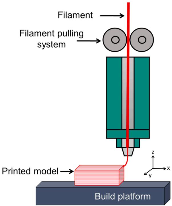
Additive manufacturing (AM) or 3D printing is a rapidly expanding advanced manufacturing technology that enables high accuracy and low-cost manufacturing of physical models and complex geometric structures. AM uses a three-dimensional design model for the fabrication through layer-by-layer printing technology that does not require the use of traditional techniques, including cutting and casting [1]. The underlying advantages of AM enable their use in the manufacturing of complex structures for various applications. AM technology is currently found in a wide range of engineering applications such as mechanical [2], biomedical [3], construction [4], aerospace [5], and food industries [6] as well as in academic research. Based on printing technology, AM has 7 different fundamental processing methods, namely, binder jetting, direct energy deposition, material extrusion, material jetting, powder bed fusion, sheet lamination, and vat photo-polymerisation [7]. Among them, fused deposition modelling (FDM) is the extrusion-based method used to manufacture polymer-based structures and models [8]. In FDM printing technology, the model to be printed is converted into a design model that is imported into the slicing software [9]. Various printing parameters need to be considered when printing such as build orientation, nozzle diameter, printing speed, layer thickness and extrusion temperature [10]. The FDM printing parameters used in the printing of polylactide (PLA) materials are shown in Table 1. FDM technology uses raw material in the form of a filament and while printing, the filament is converted to a semi-liquid form and injected into a nozzle that moves according to the instructions given by the slicing software. The extruded material from the nozzle is deposited layer by layer to print the complete model [11]. The schematic representation of the FDM process is shown in Fig. 1. Fig. 2 shows some key process parameters in FDM.
Table 1 FDM printing variables used for different PLA polymers.
| Nozzle diameter (mm) | Extrusion temperature (°C) | Bed temperature (°C) | Extrusion speed rate (mm/s) | Layer height (mm) | Reference |
| 0.4 | 220 | 70 | 90 | 0.34 | [12] |
| 0.4 | 210 | - | - | - | [13] |
| 0.4 | 230–275 | - | 30 | 0.19 | [14] |
| 0.4 | 200–230 | 50 | 30 | - | [15] |
| 0.5 | 188 | 50 | 60 | 0.4 | [16] |
| 0.5 | 180 | - | - | 0.1 | [17] |
| 0.6 | 200 | 50 | 40 | 0.1 | [18] |
| 0.8 | 230 | 60 | 30 | 0.4 | [19] |
| 1 | - | 110 | - | - | [20] |
| 0.4 | 200 | 80 | - | - | [21] |
| 0.4 | 200 | 60 | 30 | 0.3 | [22] |
| 0.4 | 180 | 40 | - | 1.5 | [23] |
| 0.3 | 220 | - | 60 | 1.75 | [24] |
| 0.8 | 220 | 60 | 60 | 1.75 | [25] |
| 0.4 | 210 | 90 | 80 | 1.75 | [26] |
| 0.4 | 220 | - | 36 | 1.7 | [27] |
text_image
Filament Filament pulling system Printed model Build platform z y x
Fig. 1. Schematic representation of the FDM process.
In FDM, thermoplastic-based filaments are the most widely used material due to their thermal characteristics. Materials such as PLA, acrylonitrile butadiene styrene (ABS), polypropylene (PP), polyetherether-ketone (PEEK), and polyamides (PA) like PA6, PA12 are commonly used filament materials [28]. The biodegradability of these materials reduces their disposal problems, which can also be recycled and used in AM [29].
FDM products are not used as functional components, rather as conceptual prototypes, due to lack of superior mechanical properties. These limitations have encouraged researchers to find a solution to establish increased strength in FDM parts. In the recent years, polymerbased fibre composites have been developed through FDM [30]. Inclusion of fibre into the thermoplastic matrix offered enhanced modulus, tensile strength, and bending strength than the neat thermoplastic material [31]. This increases the chances of utilising FDM printed materials in load-bearing applications. However, uncertainties in the FDMmanufacturing process such as the formation of voids, defects, and ineffective layer bonding increase the chances of failure in polymers and their composites [23]. The failure mechanism behind the static and dynamic loading condition of FDM printed polymers is still unclear [32]. The development of FDM technology has been significantly hampered by this issue and the implementation of this technology is also constrained.
Despite the positive aspects of FDM, the material performance is a key factor in determining the durability and reliability of these materials. The performance of FDM parts depends on various factors such as:
i- Influence of printing factors.
ii- Influence of bonding features.
iii- Influence of material and reinforcement.
iv- Influence of FDM process defects.
All these factors together make the mechanical strength analysis complicated. Additionally, 3D printed fibre composites have increased heterogeneity and anisotropic properties [33]. To support the advancement of FDM technology and the application of FDM printed materials, the complex failure nature of such materials should be examined in detail. However, FDM-based polymer and composites failure mechanism has been investigated for tensile strength [34], flexural strength [35], impact strength [19], compression strength [30] and thermos-mechanical behaviour [36] under static loading conditions. For load-bearing applications, materials need to withstand both mechanical and environmental stress [37,38]. Cyclic loading on materials leads to failure under fatigue. In such a case, it is critical to understand the fatigue behaviour to increase the durability and reliability of the materials.
This article aims to review the fatigue behaviour of polymeric materials produced by FDM. The primary objective of this review is to explain the importance of fatigue in 3D printed materials based on the recently reported work in this field. The review also focuses on the novel 3D printed architectural-cellular-material’s (ACM) fatigue behaviour. This is the first article to assess the fatigue behaviour of FDM-based polymeric materials, which sought to explain major printing factors affecting fatigue life, to understand the underlying fatigue failure mechanism and their impact on 3D printed materials.
2. Fatigue and fatigue testing in polymeric materials
The development of polymeric materials enables their application in various structural and load-bearing applications. Fatigue may occur in structural components due to cyclic stress, which leads to catastrophic failure at a lower stress than in the case for the normal static mechanical loading [39]. Understanding fatigue behaviour and its damage mechanisms are essential for assessing emerging materials in various appli cations to determine their durability and long-term reliability [40]. It is essential to analyse the fatigue behaviour of polymeric materials due to their increased use in applications such as passenger aircraft and automobiles where ensuring the safety of human life is critical. Fatigue tests for polymers are performed in repeated loading and unloading conditions subject to compression, tension, bending, torsion, or a combination of these stresses [41]. During the fatigue test, the load is applied as tension – tension, compression – compression and compression – tension or compression – tension-type. Although there are different types of fatigue tests in practice, load controlled high cycle and strain-controlled low cycle type of fatigue tests are preferred to be the two most common fatigue tests. High-cycle testing involves loading under the viscoelastic regime, while low-cycle fatigue testing involves plastic deformation [42]. The standards followed for conducting fatigue tests are listed in
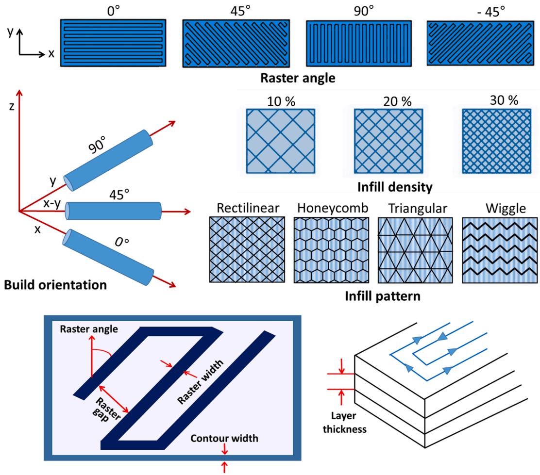
Fig. 2. FDM process parameters.
Table 2 Standards followed for polymer fatigue testing.
| Type of fatigue test | Standard | Type of material |
| Uniaxial fatigue (tension or compression) | ASTM | Polymer |
| D7791 | ||
| Tension fatigue | ASTM | Polymer matrix composite |
| D3479 | ||
| Uniaxial flexural fatigue (Three- or four-point bending) | ASTM | Polymers |
| D7774 | ||
| Fatigue delamination growth | ASTM | Polymer matrix composite |
| D6115 | ||
| Statistical analyses of fatigue data | ASTM | Metals/Polymers |
| E739 | ||
| Strain controlled fatigue - uniaxial forces | ASTM | Homogeneous materials |
| E606 | ||
| lamina/laminate dynamic properties | ASTM | Polymer matrix composite |
| D4762 | ||
| Bearing fatigue response | ASTM | Polymer matrix composite |
| D6873 | ||
| Open hole fatigue (tension-tension, compression-compression, or tension-compression cyclic loading) | ASTM | Polymer matrix composite |
| D7615 | ||
| Fatigue crack propagation – notched condition (tension-tension) | ISO 15850 | Polymer |
| Axial tensile fatigue test/flexural bend test (tension-tension) | ISO 13003 | Polymer matrix composite |
Table 2. The cyclic loading conditions in different applications affect the durability and strength of the polymeric materials. Fatigue behaviour of a material is analysed using a cyclic stress-strain curve (S-N curve) that is developed using a set of stabilised hysteresis loops at different strain amplitudes [43,44]. Through the S-N curve, the endurance limit of the material can be determined, which is the maximum stress level where the material withstands cyclic loading without failure. Material surface characteristics such as roughness, damage, and residual stresses in the materials are critical in affecting the endurance limit [45]. In addition to the material surface properties, factors such as the type of load and the volume of material are also the key factors affecting the endurance limit [46]. The endurance limit enables the designer to set the maximum cyclic loading stress for a material for a specific application, however, the endurance limit is practically not applicable for many materials [47]. Notably, in the case of polymers, the physical theories available had a deficiency in explaining the mechanical S-N behaviour since empirical methods, along the lines of those used in metal fatigue, were used to evaluate polymer fatigue behaviour [48,49].
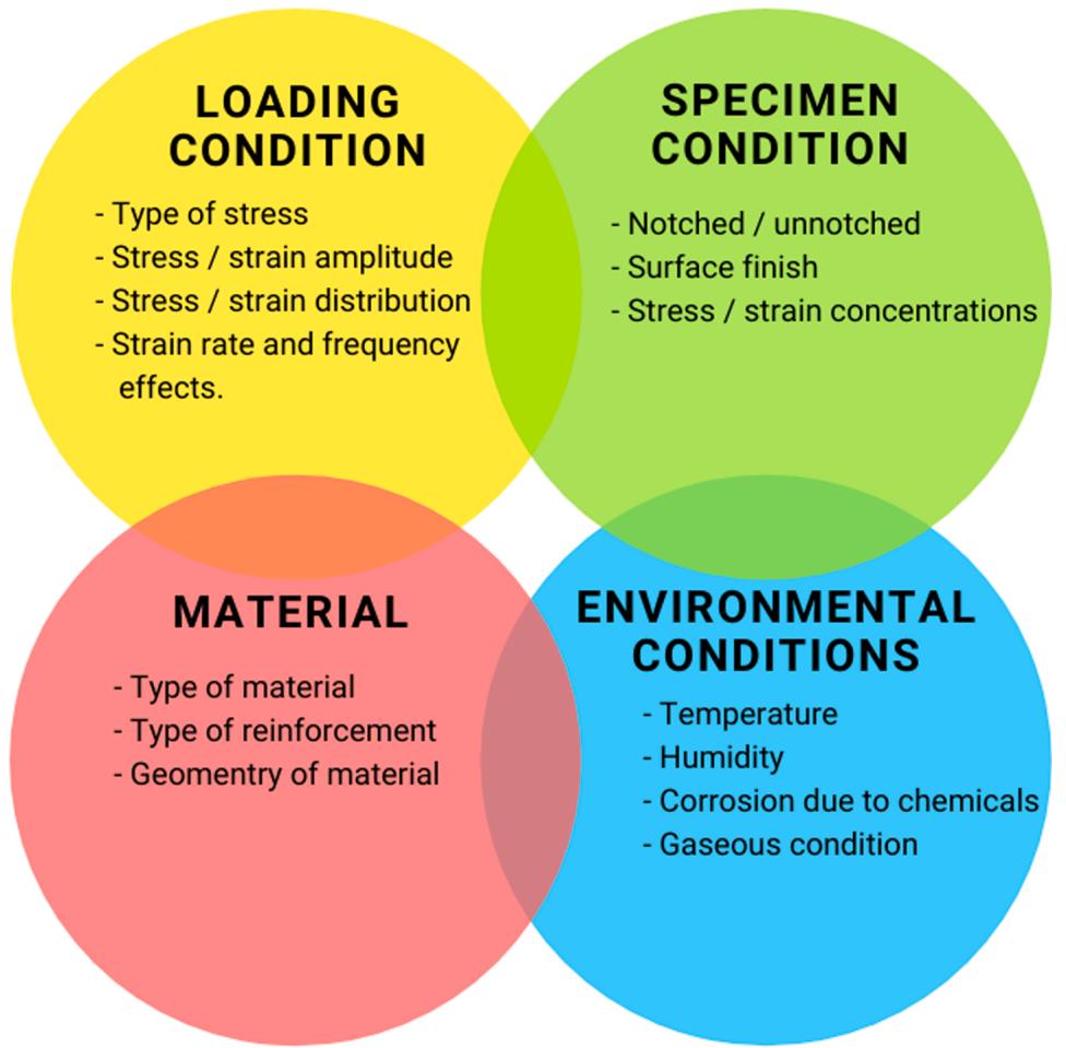
Fatigue failure of polymers is inherently due to the accumulated damage or due to the growth of the defect to a critical dimension. The fatigue behaviour of polymeric materials is substantially influenced by the physical properties, environmental conditions, and mechanical loading factors (Fig. 3). Pruitt et al. [50] reported that the molecular structural variables such as molecular weight, distribution, crystallinity, crosslink density, chain entanglement density and reinforcement characteristics of polymeric materials are important factors for the actual fatigue behaviour. Mechanical loading factors such as stress amplitude, strain, mean stress, stress-strain ratio, cyclic frequency, self-heating effects, and a notch or stress concentration effects also have a significant
venn diagram
| Condition | Description |
|---|---|
| LOADING CONDITION | - Type of stress, - Stress / strain amplitude |
| LOADING CONDITION | - Stress / strain distribution, - Strain rate and frequency effects. |
| SPECIMEN CONDITION | - Notched / unnotched, - Surface finish, - Stress / strain concentrations |
| MATERIAL | - Type of material, - Type of reinforcement, - Geometry of material |
| ENVIRONMENTAL CONDITIONS | - Temperature, - Humidity, - Corrosion due to chemicals, - Gaseous condition |
| ENVIRONMENTAL CONDITIONS |
Fig. 3. Factors affecting fatigue life in polymeric materials.
impact on polymer fatigue characteristics [51]. The mean stress is the average of the maximum stress and the minimum stress (σmin), whereas the stress ratio (R) is the ratio of the minimum stress to the maximum stress. The stress ratio describes the loading nature during the fatigue condition, i.e. ∞ indicates that the cycle is in the compression-to-compression region, - ∞ < indicates that the cycle is in the tension -to- compression region and indicates that the cycle is in the tension-to-tension region [52]. At high cycle-frequency, polymers may soften or melt, resulting in fatigue failure due to thermal softening [53]. Fatigue studies on the polymers are based on uniaxial loading conditions, which are tension-tension, tensioncompression, and compression to tension or strain-controlled modes. Biaxial fatigue, triaxial fatigue, multiaxial fatigue, combined bending and torsional fatigue are some of the other types of tests used in complex fatigue analysis [49,48]. As reported by Amjadi and Fatemi [54], polymer fatigue analysis based on multiaxial stress is rare. In many cases, multiaxial stress in polymers are unavoidable due to multiaxial loading conditions and notched as well as stress concentrated multiaxial loading conditions. It is also difficult to anticipate multiaxial fatigue in polymers.
flowchart
graph LR
  A["stage I: fiber matrix"] --> B["stage II: propagation"]
  B --> C["stage III: damage"]
  C --> D["stage III: failure"]
    style A fill:#f9f,stroke:#333
    style B fill:#bbf,stroke:#333
    style C fill:#f9f,stroke:#333
    style D fill:#bbf,stroke:#333
    subgraph Stage I
        E["fiber"]
        F["matrix"]
        G["inhibition"]
    end
    subgraph Stage II
        H["propagation"]
    end
    subgraph Stage III
        I["damage"]
    end
  J["crack initiation period"] --> K["craze"]
  K --> L["craze growth"]
  L --> M["micro crack growth"]
  M --> N["macro crack growth"]
  N --> O["crack growth period"]
  O --> P["failure"]
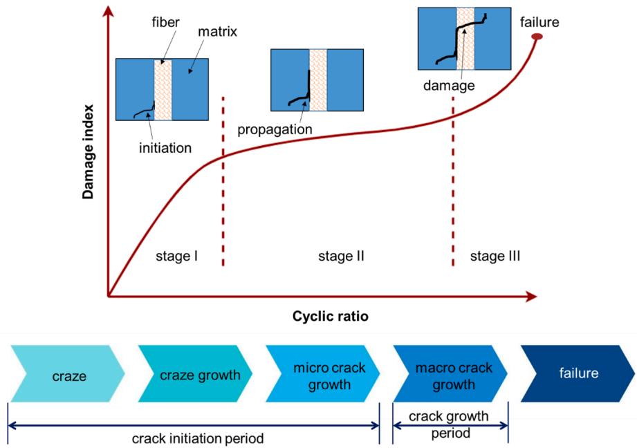
Fig. 4. Stages of fatigue failure.

flowchart
graph TD
  A["FDM Filament"] --> B["FDM build parameters"]
  B --> C["Part positioning"]
  C --> D["Printing environment"]

  A --> A1["Polymer blend"]
  A --> A2["Colour"]
  A --> A3["Density"]

  B --> B1["Infill percentage"]
  B --> B2["Raster orientation"]
  B --> B3["Raster gap"]
  B --> B4["Layer height"]
  B --> B5["Shell number"]
  B --> B6["Extrusion speed"]
  B --> B7["Travelling speed"]

  C --> C1["Orientation with respect to build platform"]
  C --> C2["XY position on build platform"]

  D --> D1["Extruder temperature"]
  D --> D2["Extruder nozzle diameter"]
  D --> D3["Build platform temperature"]
  D --> D4["Envelope temperature"]
Fig. 5. FDM parameters affecting fatigue life.
Unlike metals, polymers are heat sensitive and viscoelastic, and under this circumstance the polymer can easily melt or undergo thermal rupture [55]. In general, fatigue failure of polymeric materials begins with the initiation of micro defects and crazing in highly stressconcentrated areas. Crazing is caused by internal and external surface defects, voids and poorly bonded matrix interfacial areas, which have a critical effect on the mechanical strength and consequently cause deformation [56]. Continued cyclic loading causes plastic deformation and crack propagation in polymers until the critical crack size is reached, which leads to a sudden catastrophic failure. The polymeric material fracture under fatigue can be studied in detail by analysing the initiation and propagation of cracks [57]. The fatigue failed/fractured polymer surface consists of two distinct types of crack propagation: continuous and discontinuous crack propagation. Discontinuous type of crack propagation is initiated by the development of a single crack at a low-stress intensity or at a non-positive stress ratio (R ≤ 0). Rise in the stress increases the discontinuous crack propagation that can be understood by the generation of continuous parallel striation marks on the fractured surface [58]. The crack propagation point and the initiation point are important as they can be delayed by strengthening the polymer with reinforcement materials [59] such as fibres or particulate filler. Reinforcement properties such as reinforcement type, reinforcement amount, fibre length, fibre orientation direction, processing method, and bonding features are also important for polymer composite fatigue resistance [52,60,61]. Reinforcement in polymers increases the heterogeneous characteristics in the composite, which lead to the anisotropic performance of the composite. Typical fatigue failure mechanisms in polymer fibre composites include matrix cracking, fibre debonding, delamination, and fibre layer separation [62].
The fatigue failure mechanism in polymer fibre composites consists of three stages. (Fig. 4). Stage I is a fibre matrix debonding, wherein the fibre tends to debond from the matrix in poorly bonded regions, fibre misaligned regions, matrix rich regions, or from surface defects such as voids and pores. In stage II, the fibre delaminates from the matrix. The final stage III is damage growth, where the fibre fails due to the localised damage propagation in stage I and stage II [52]. Unlike metals, it is difficult to predict the fatigue failure of polymers owing to the high dependency on temperature and load frequency [63]. Fatigue failure analysis is a time-consuming process that requires several sample materials. To simplify the analysis, a thermographic method (TM) has been introduced through which the fatigue limit and the S-N curve can be predicted in regard to the temperature variation of the specimen during the test [64]. This method was first proposed by La Rosa and Risitano in 2000 [65]. Recently, Santonocito [66] used the Static Thermographic Method (STM) to evaluate the fatigue properties of 3D printed polyamide-12 material. The fatigue tests were performed at a stress ratio of 0.1, a frequency of 3 Hz and a stress amplitude of between 28 MPa and 30 MPa. The average endurance limit of 29 MPa was determined at the limit stress level by temperature variation through STM.
3. Fatigue evaluation of 3D-FDM printed polymeric materials
3.1. Polymers
In the 3D-printing of polymers, FDM has demonstrated its ability to produce polymers with comparable results to conventional manufacturing processes, but the formation of voids and imperfections in FDM printed polymers is inevitable, which could lead to failure under loading. In addition, fatigue data for AM polymers are scattered, which further make analysis difficult due to the manufacturing defects and uncertainty in AM process [67]. The strength of the FDM printed polymer depends on both the printing condition and the characteristics of the polymer. Furthermore, layer-by-layer addition of polymer in the FDM process imparts anisotropic material properties to the printed polymer, which affect the strength of the material. FDM printed materials are not isotropic as they do not have the same strength in all directions due to layer-to-layer adhesion variation and print orientation. However, there is enough literature available to understand both the strength and the failure mechanism of the FDM printed polymer when exposed to mechanical loading [68,69]. Crucial information on the influence of FDM printing parameters on the performance of the printed material is also available [9,70]. The fatigue strength of polymers also depends on FDM printing conditions. As a result, research aimed at understanding the fatigue behaviour of FDM printed polymers has increased steadily over the recent years. However, the anisotropic characteristics of the FDM printed parts may cause problems if they are not controlled, as their homogeneity is not assured [71]. Nevertheless, this can be controlled through the use of optimised FDM printing parameters [10]. FDM printing parameters that affect the fatigue life of printed polymers are shown in Fig. 5.
scatterplot
| log10(Number of cycles to failure) | Maximum Stress (MPa) | Direction |
|---|---|---|
| 2.8 | 21.0 | -45°/45° |
| 3.0 | 18.0 | 0°/90° |
| 3.2 | 18.5 | -45°/45° |
| 3.4 | 16.0 | 0°/90° |
| 3.8 | 14.0 | -45°/45° |
| 3.9 | 12.0 | 0°/90° |
| 4.6 | 9.0 | -45°/45° |
| 4.7 | 8.0 | 0°/90° |
| 4.8 | 8.0 | -45°/45° |
| 4.9 | 8.0 | 0°/90° |
scatterplot
| log10(Number of cycles to failure) | Maximum Stress normalised over UTS (-45°/45°) | Maximum Stress normalised over UTS (0°/90°) |
|---|---|---|
| 3.0 | 0.9 | 0.9 |
| 3.2 | 0.8 | 0.8 |
| 3.8 | 0.6 | 0.6 |
| 4.6 | 0.4 | 0.4 |
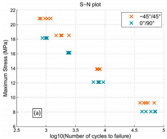
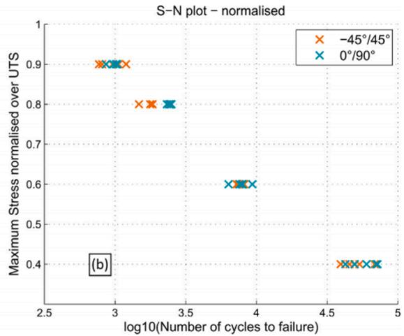
Fig. 6. Fatigue S-N plot of ABS printed at different raster orientations – (a) raw, (b) normalised over UTS [82].
3.1.1. Polylactide (PLA)
Ezeh and Susmel [72] investigated the fatigue strength of the PLA material fabricated through FDM. The study analysed the influence of the manufacturing direction (0◦, 30◦, and 45◦) and superimposed static stress. During the fatigue loading, the printed PLA material exhibited three distinct failure mechanisms: (i) filament cracking, (ii) layer debonding, and (iii) filament debonding. The scatter ratio of the endurance limit at different angles of manufacturing was found to be minimal, therefore the authors stated that the manufacturing direction in the design of 3D PLA materials could be neglected. On analysis of the S-N curve at varying R (− 1, − 0.5, 0, and 0.30), the authors concluded that in the fatigue design of 3D PLA, non-zero mean stress can be considered in the fatigue assessment by considering the maximum stress in the cycle. In another study, Ezeh and Susmel [73] reported that the fatigue behaviours of conventionally manufactured PLA and AM-FDM manufactured PLA were similar. In addition, the authors found that the PLA material printed at an infill density of less than 100% behaves like a notched material, which contributed to the reduction of the overall fatigue strength of the printed PLA. Both the investigations of Ezeh and Susmel [72,73] revealed the PLA fatigue behaviour on varying raster orientation as well as stress concentration effect due to notching. The influence of raster orientation is well defined with respect to zero mean stress but the interaction among the other FDM parameters was not considered.
Jerez-Mesa et al. [74] investigated the impact of FDM printing parameters on the fatigue strength of PLA material. The PLA material was printed at varying layer heights (0.1, 0.2, and 0.3 mm), nozzle diameter (0.3, 0.4, and 0.5 mm), fill density (25, 50, and 75%) and printing speed (25, 30, and 35 mm / min). From fatigue strength analysis with respect to different printing parameters, it was concluded that fill density, nozzle diameter, and layer height were the most influential 3D printing parameters affecting the fatigue life of the PLA material. Gomez-Gras et al. [75] carried out a rotating bending fatigue test on FDM printed PLA material and reported fill density as the most influencing factor in affecting the PLA fatigue life followed by the layer height. Interestingly in both the investigations [74,75], maximum fatigue life was achieved with a 75% infill density, 0.5 mm nozzle diameter, and 0.3 mm layer height. The similarity in the results of references [74,75] suggests to follow the same range of infill density, nozzle diameter, and layer height to achieve better fatigue life in PLA material, however, the endurance limit varies. In both investigations, the influence of raster orientation was not investigated. However, the raster orientation of 45◦ was reported to generate maximum fatigue life and endurance limit in the references [76,77].
In a separate study, PLA material was printed by FDM at three build directions (X, Y, and 45◦) and tested for fatigue strength (Tension-Tension). PLA printed at 45◦ orientations showed increased fatigue life, i.e. approximately 1380 cycles at 50% of its ultimate tensile strength (UTS), compared to the PLA printed in two other directions. Additionally, the same material had higher strain energy of ca. 2050 kJ m− 3 until failure at 1380 cycles [76]. Letcher and Waytashek [77] reported that the PLA material printed at the raster orientation of 45◦ had the maximum fatigue endurance limit, whereas, the minimum endurance limit was observed for the PLA material printed at a raster orientation of 90◦. Interestingly, Arbeiter et al. [78] reported that PLA printed at 0◦/90◦ fibre orientation had a better fatigue life. However, the fatigue fracture characteristics of FDM printed materials are not highly dependent of orientation. This was verified by very identical crack initiation, crack growth initiation, and failure curves in all fibre orientation (0◦, 90◦, and 0◦/90◦). The results of these three references [76–78] reveal that the fatigue life and failure characteristics were not anticipated to be similar at all raster orientations.
Ezeh and Susmel [79] using notched FDM printed PLA materials analysed the crack propagation during fatigue loading. In the notched PLA material, the propagation of crack due to fatigue stress followed an irregular path along with the orientation of the filaments. The fatigue life of the notched PLA material decreased due to increased stress concentration in the sharp notch. Similar to the un-notched PLA material failure mechanism [72], the notched PLA exhibited three distinct failures, such as rectilinear filament cracking, de-bonding between adjacent filaments, and de-bonding between adjacent layers [79]. Although through FDM it is possible to print intricately shaped polymeric materials, the stress concentration in sharp corners and edges of the printed material is a major issue, which could increase the chances of fatigue failure.
3.1.2. Acrylonitrile butadiene styrene (ABS)
Zhang et al. [80] investigated the fatigue behaviour of FDM printed ABS material by applying reverse stress through a rotary fatigue tester. An increase in the fatigue load from 30 N to 60 N reduced the fatigue life cycles from ca. 3800 cycles to 130 cycles. The maximum crack size was 0.75 mm, which was calculated based on Paris law, and the fatigue cracks growth was at a rate of 0.0341 mm/cycle. At low load, cracks began to initiate and at high load, cracks began to propagate, which led to fatigue fracture.
natural_image
Microscopic surface texture image with 50 μm scale bar, showing irregular granular structure (no text or symbols)
natural_image
Microscopic surface texture image showing layered structures with 100μm scale bar (no text or symbols beyond label)
natural_image
Microscopic cross-section of layered material showing layered structure with 200μm scale bar (no text or symbols beyond label)
natural_image
Microscopic view of a textured surface with granular patterns, scale bar indicating 500μm (no text or symbols present)
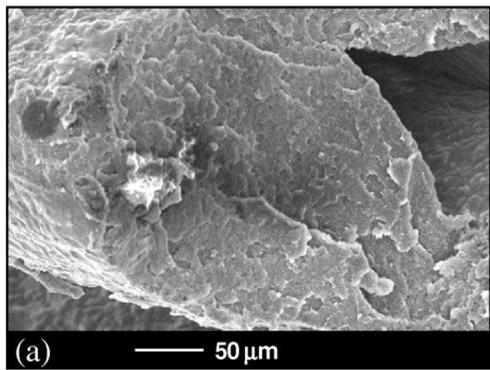
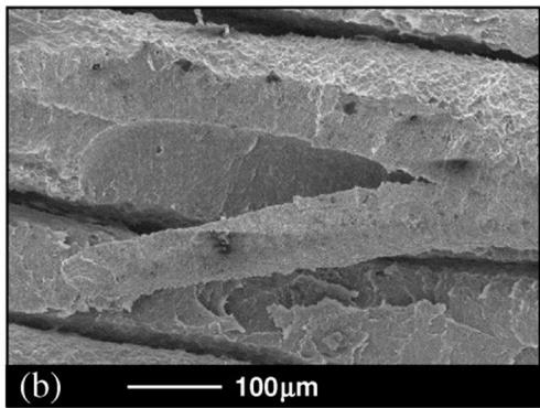
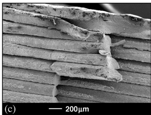
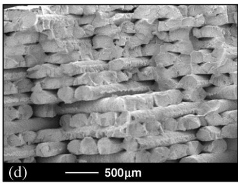
Fig. 7. Fatigue failed ABS SEM images (a) crazing, (b) fibre cracking, (c) delamination, and (d) void changes [88].
Ziemian et al. [81] reported that longitudinal (0◦) and default (+45/ − 45◦) raster orientations are effective for increasing ABS material fa tigue life rather than diagonal (45◦) or transverse (90◦) orientations. FDM fabricated ABS material with different raster orientations (− 45◦/ 45◦ and 0◦/90◦) was investigated for fatigue characteristics by Jab et al. [82]. Tests were performed on tension to tension-type fatigue loading at a stress ratio of 0.1 and a frequency of 5 Hz. The authors compared the fatigue life of the FDM printed ABS with injection moulded ABS. At a stress of 10 MPa, the injection moulded ABS had approximately 6 million cycles to failure [83] but at the same condition, the FDM printed ABS had 60,000 cycles to failure. When stress was normalised over the ultimate tensile strength, variation in the raster angle showed no effect on fatigue strength, in fact, similar fatigue strength was observed. The fatigue S-N plot for the corresponding orientations is shown in Fig. 6.
Domingo-Espin et al. [84] performed a rotating flexural fatigue test on the FDM printed ABS material with varying infill patterns (rectilinear and honeycomb) and studied the influence of layer height, nozzle diameter, infill density and printing speed. The result showed that the infill density has maximum contribution in affecting the fatigue life of ABS material having rectilinear and honeycomb infill patterns. Increased infill density leads to an increase in fatigue life of ABS. Lee and Huang [85] investigated the cyclic loading effect on the strain energy of FDM printed ABS-(P400) and ABS-(P430) materials and compared the results with the ABS wire data. The printed ABS-(P400) showed a strain energy in the range of 3.4–19.7% of the strain energy of ABS-(P400) wire material, while the strain energy of the printed ABS-(P430) was 1.8–7.4% of the strain energy of ABS-(P430) wire material. ABS-(P430) suffers fatigue failure in the order of approximately 1,000 cycles at 40% of its UTS and 60% of its UTS for ABS. Corbett et al. [86] studied the influence of the FDM-process parameters on the ABS material fatigue life. ABS printed at a smaller layer height (0.2 mm) in flat X orientation showed a better fatigue life. Padzi et al. [87] correlated the fatigue life (T-T) of the FDM printed and injection moulded ABS material and stated that 3D printed products were not appropriate for industrial applications. The moulded ABS displayed a fatigue life of 911, 2645, and 26,948 cycles at 80%, 60%, and 40% of UTS, respectively, which is 55%, 39%, and 30% higher than the printed ABS material’s fatigue life. FDM printed specimens under fatigue loading displayed multiple failure modes such as void changes, delamination, crazing, and fibre cracking [88] (Fig. 7). Mishra et al. [89] found variation in the failure mechanism on static and cyclic loading conditions of ABS material printed through FDM. Under static loading, the failure in the ABS was in the perpendicular direction against the applied load but under cyclic loading, the failure was in a zigzag manner. The failure mechanism in the FDM printed materials was because of the initiation of cracks in the weak surface or between poorly bonded layers.
3.1.3. Polyethylene terephthalate glycol (PETG)
Dolzyk and Jung [90] carried out a uniaxial fatigue test on FDM printed PETG material at four raster directions- longitudinal (0◦), transverse (90◦), diagonal (45◦) and crosshatched (45◦). During the fa tigue test, PETG samples were subjected to a stress ratio of R = 0.1 at 90, 80, 70, and 60% of UTS. Stronger inter-layer bonding in the PETG samples reduced the anisotropic properties. Sample printed at longitudinal orientation had maximum fatigue life at 90% loading condition. The sample printed at crosshatched and longitudinal orientation showed a similar fatigue failure mechanism that was evident through a similar S-N curve. At the lowest loading condition (60%), the sample printed at diagonal orientation had a maximum life-cycle failure of ca. 20,000 cycles. The fatigue fracture mechanism of the PETG samples varied with respect to the orientation of the raster, e.g. the samples printed in longitudinal orientation experienced progressive crack propagation, whereas in the transverse direction, layer delamination was noted, and a ductile failure was noted on the crosshatched print samples. In the recent years, PETG has been used as an alternative to PLA and ABS polymers. However, the fatigue results concluded by Dolzyk and Jung [90] are fascinating but there are many gaps, such as no data reported on the effect of FDM process parameters, and fatigue life at different load types. Interestingly, the diagonally-oriented sample showed a reduced fatigue life at a higher load, but at a lower load, it had the highest fatigue life. This result is critical for the design of PETG material for long durability at low load conditions, although the discussion on this subject is very limited, which creates a necessity to study diagonally-oriented PETG samples under loading conditions of less than 60%.
Table 3 Fatigue testing results for different materials.
| Type of fatigue test | Matrix | Reinforcement | Frequency (Hz) | Standard | Remarks | Reference |
| Tension-tension cycling | ABS | - | 0.25 | ASTM D3479 | The 45°/45° raster orientation had a better fatigue life | [110] |
| Tension-tension cycling | ABS | - | 0.25 | ASTM D7791 | Microscopic failure mechanisms displayed the higher tension fatigue performance of the bidirectional specimens with +45/-45° layering pattern. | [111] |
| Tension - tension cycling | ABS | - | 0.25 | ASTM D7791 | The +45°/-45° raster orientation specimens survived the maximum number of cycles to failure compared to other orientations (0°, 45°, and 90°). | [81] |
| Rotating flexural fatigue test | ABS | - | Rotational movement of 2800 min $^{-1}$ | ASTM D7774* | The infill density is the most significant parameter for both Rectilinear and Honeycomb patterns. In addition, the samples printed with the honeycomb pattern showed longer lifespans. | [84] |
| Tension - tension cycling | ABS | - | 0.25 | ASTM D7791 | The default bidirectional (+45°/-45°) samples had the longest life span at each normalised stress level. | [88] |
| Three-point bending cycling | PA6 | - | 5 | - | The XZ build orientation of PA6 reveals a greater overall fatigue life compared to XY build orientation. | [91] |
| zero-to-tension manner | PCU | - | 5 | ASTM E606 and D4482* | SEM images of the fatigue fracture surface of IM and FDM samples are almost indistinguishable, which shows a very solid infill for FDM samples with adequate bonding between lines and layers. | [94] |
| Tension - tension cycling | Nylon | FG, Kevlar, and CF | 5 | ASTM D7791 | The specimens with nylon matrix, triangular filling pattern, and matrix density of 20%, reinforced with carbon fibre at 0°, displayed better fatigue performance and significantly increased the number of cycles before specimen rupture. | [102] |
| Tension - tension cycling | Nylon | CF, Kevlar, and FG | - | ASTM E606 M | The strongest specimens for all the load-ranges were the nylon-CF that endured the maximum number of cycles. | [112] |
Note: CF: carbon fibre; FG: Fiberglass; PCU: polycarbonate urethanes, IM: Injection Moulding. *developed custom shape based on this standard.
3.1.4. Polyamide
The effect of the build orientation on 3D printed polyamide 6 was investigated by Terekhina et al. [91]. The specimens were printed in the unidirectional raster orientation (0◦) and at two different build orientations, namely, such as flat orientation (XY plane) and the edge orientation (XZ plane). During cyclic loading, two different failure mechanisms were observed in both printed polyamides. In the first 100 cycles, due to its viscous nature, the polymer lost its stiffness and therefore the material showed small variation in their shape and size. In the second, a rapid propagation of damage was noted. Interestingly, the fatigue failure of the printed polyamide initiated due to the microdelamination fatigue cracks in the layer interface. Increased porosity (13%) in polyamide printed at XY build orientation reduced the fatigue life compared to polyamide printed at XZ build orientation. In another study, Terekhina et al. [92] compared the fatigue properties of PA12 material manufactured by FDM and selective laser sintering (SLS) by conducting three-point cyclic bending tests. The FDM produced PA12 showed a 40% improvement in fatigue properties (longer end-of-life and lower degradation rate) than the SLS-PA12 material. This investigation proves the effectiveness of FDM made PA material against the fatigue load when compared to SLS made material. It would be interesting to compare the fatigue results of PA material produced using different AM manufacturing methods, which could help identify the appropriate fabricating AM process for such materials.
3.1.5. Polycarbonate (PC)
Puigoriol-Forcada [93] investigated the fatigue life of FDM printed PC material. Samples were printed in three different printing directions (XY, YZ, and XZ), and the flexural fatigue test was performed at 20, 40, 60, and 80% UTS loading conditions with R = 0.5 and R = 1. The maximum life cycle was recorded for the sample that was printed in YZ direction followed by the sample that was printed in XZ direction. The sample that was printed in the XY direction exhibited minimum life cycle. This phenomenon has been attributed to the distribution of the load on the deposited layers. In XZ direction, the maximum load was distributed on the interlayer material leading to rapid fatigue failure.
However, this study did not disclose the effect of layer bonding and other FDM parameters on the fatigue life of the PC. The limited fatigue study in FDM printed PC material opens up opportunities for further research in this area, which could allow the application of PCs in loadbearing applications.
Miller et al. [94] compared the fatigue life of polycarbonate urethane material produced by injection moulding and the FDM method. Three different grades of polycarbonate urethane have been used, such as AC-4075A, AC-4085A, and AC-4095A. The FDM sample was printed at a layer height of 0.15 mm, an extrusion width of 0.3 mm, and a 100% rectilinear infill. The displacement controlled fatigue test was performed through the tension-relaxation type of fatigue loading. All three graded FDM printed material had a better fatigue life than the injection mould materials. The strain amplitude of the AC-4085A material was higher during the runout of 1 million cycles. The FDM printed AC-4085A material had a strain amplitude of 60% over 1 million cycles, while the injection moulded AC-4085A material has a strain amplitude of 50%. Both FDM printed and injection moulded materials with a fatigue life of between 400,000 and 500,000 cycles exhibited similar fatigue fracture surfaces.
3.1.6. Polyetherimide
Fischer and Schoppner ¨ [95] studied the post-treatment effect of the FDM-printed polyetherimide (Ultem 9085) material. Samples were printed in three build orientations (X, Y, and Z build directions). Chemical vapour treatment on the sample was performed by exposure to chloroform vapour. Although the tensile strength was increased during the treatment process, there was no change in the fatigue life of the printed Ultem. Samples printed at build orientations X and Y had a longer fatigue life. At 40% of the UTS, sample printed at X direction had ca. 8270 cycles-to-failure and for Y and Z directions it was ca. 8340 and ca. 4200 cycles-to-failure, respectively.
To the best of the knowledge of the authors, it is the only available study noted on the effect of polymer surface treatment on fatigue life. However, there is no influence of surface treatment of polymer on the fatigue life. However, polymer blending or addition of plasticisers in
FDM filaments could result in increased fatigue life and this is suggested by noticing the increment in the mechanical properties of FDM printed polymers [96–98].
3.1.7. Polyether-ether-ketone (PEEK)
To the best knowledge of the authors, there are no results available on the fatigue characteristics of FDM based PEEK materials. In the recent years, PEEK has been used in aerospace applications owing to their lightweight nature and because it is a well-suited matrix for the carbon fibre-based composites [99]. The FDM printed PEEK material had a flexural modulus of 2.43 GPa and flexural strength of 132.37 MPa, which was higher than the FDM printed ABS and SLS printed PA material [100]. Wu et al. [101] also found maximum tensile, compression, and bending strength on FDM-based PEEK material, which is 108%, 114%, and 115% higher than FDM-based ABS material. Thus, it can be anticipated that when compared to other FDM printed thermoplastics, PEEK can deliver better fatigue resistance and fatigue life.
3.2. Polymeric fibre composites
Defects in composite materials may accidentally occur during loadbearing operations and also during the manufacturing process. Growth of these defects under continuous loading condition lead to fatigue failure. Under fatigue loading, fibre composites exhibit distinct behaviour that differs from metals and neat polymers. Fatigue strength of fibre composites is a function of fibre properties such as fibre type, loading percentage, fibre matrix bonding, fibre surface properties, fibre length, and fibre orientation [52]. Table 3 highlights the important results of the fatigue behaviour of FDM based materials.
Pertuz et al. [102] fabricated nylon composites with three different continuous fibre reinforcements; carbon fibre, glass fibre, and Kevlar fibre. Composites were printed with a triangular filling pattern and a filling percentage of 20%. Fibres were reinforced in isotropic and concentric type layering, in isotropic type reinforcement, fibre orientation was varied as 0, 45, and 60◦. The uniaxial fatigue test was carried out at the loading conditions of 95, 90, 85, and 80% of UTS. Compared to glass and Kevlar fibre reinforcement, carbon fibre reinforcement printed at 0◦, triangular filling pattern, and 20% filling showed superior fatigue response. This work is comprehensive enough to understand the fatigue characteristics of FDM printed composites but the fatigue failure mechanism of the tested fibre composites has not been adequately explained.
Travieso-Rodriguez et al. [103] investigated the fatigue behaviour of PLA-wood composites produced by FDM at varying layer heights (0.2, 0.3, and 0.4 mm), infill densities (25, 50, and 75%), nozzle diameters (0.7, 0.6, and 0.5 mm), infill patterns (rectilinear and honeycomb) and extrusion velocities (25, 30, and 35 mm/s) at 8% of wood fibre reinforcement. However, no consideration was given for the key FDM parameters building orientation and raster angle. The rotating bending fatigue test was performed and compared to neat PLA, PLA-wood fibre composite showed poor fatigue strength due to a lack of proper fibre matrix adhesion and increased void formation. The honeycomb-filling pattern with a layer height of 0.4 mm, a nozzle diameter of 0.7 mm, and a filling density of 75% was reported as the optimum FDM printing factor to achieve the maximum number of cycles to failure. Brooks et al. [104] investigated PLA carbon fibre composite fatigue strength. Composites were printed with 50 wt% of carbon fibre reinforcement at horizontal orientation and varying infill densities of 25 and 90%. Composite printed with 25% infill density had a better fatigue life, which takes 400 cycles to fail at maximum UTS, while composite printed at 90% infill density failed after nearly 300 cycles. In the references [103,104], the authors demonstrated the fatigue life of fibre composites with constant fibre weight percentages. Instead of that, the authors could have tested composites with varying fibre weight percentages, to observe the influence of fibre weight percentage as well as the variation in fatigue life.
area chart
| Region | Number of cycles | Stress Level |
|---|---|---|
| Region I | 0 | Fiber breaking |
| Region II | 1 | Fiber debonding & matrix cracking |
| Region III | 2 | No initiation, crack arrest |
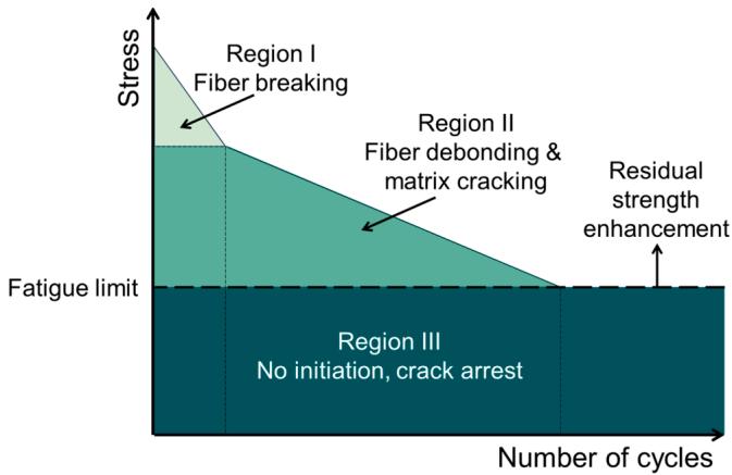
Fig. 8. Schematic of the SN curve of fibre composites. Figure inspired by the work of [109].
Essassi et al. [105] developed PLA/flax fibre-based sandwich composites with an auxetic core of 4 different auxetic core densities (8.3%, 16.7%, 25.1% and 33.5%). Fatigue behaviour of the fabricated PLA/flax fibre sandwich composites was investigated by conducting cyclic bending tests. It was observed that the sandwich composites with a lower core density of 8.3% had a higher fatigue life. The authors reported three stages of failure for the sandwich PLA/flax fibre composite beam under fatigue loading, from loss of stiffness to ultimate failure. The first stage involves a reduction in the loss of stiffness due to the initiation of damage. In the second stage, there is reduced loss of stiffness, however, the damage propagation is high. The third stage involves a sudden decrease in loss of stiffness and complete failure of the specimen. Through this investigation, it was possible to understand the fatigue nature of sandwich fibre composites due to fatigue damage initiation – damage spread – failure.
Only a few studies have been conducted on the fatigue properties of FDM-based polymer fibre composites. This highlights the lack of research data on the fatigue properties of FDM-based fibre composites. Generally, FDM printed fibre composites exhibit comparable results with the virgin material and the optimisation of FDM variables and fibre properties could provide increased mechanical strength [106]. A significant disadvantage for the FDM printing of fibre composites is the formation of voids [107], which increases the chances of crack propagation under critical cyclic loading condition [108]. Fig. 8 is a schematic of the S-N failure curve of fibre composites.
3.3. 3D printing and fatigue evaluation in biomedical applications
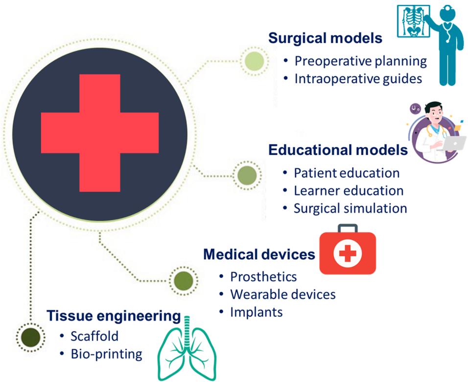
Due to customised manufacturing at a low cost of production, 3D printing technology has attracted attention from both academic and industrial research. 3D printing is slowly being introduced in nearly all fields and sparking a revolution in manufacturing. With inherent advantage such as the ability to print complex geometry in limited time, 3D printing technology enables the development of polymeric material for biomedical applications [113]. Recent 3D printing technology projects for medical applications can be classified into four broad research areas: i) pathological organ development; ii) permanent non-bioactive implant development; iii) bioactive and biodegradable scaffold development; and iv) tissue and organ printing research [114,115]. Choong et al. [116] recently addressed the adaptation of 3D printing technology to meet the demand for medical devices and equipment such as respirators, masks, insulation centres, medical manikins, and nasopharyngeal swabs in the ongoing COVID-19 pandemic situation. Fig. 9 shows the applications of 3D printing in biomedical arena.
In the field of tissue engineering, 3D printing technology enables the production of tissue scaffolds with controlled pore size and structure [117]. 3D printed scaffolds are used in various biomedical applications
flowchart
graph TD
  A["Surgical models"] --> B["Preoperative planning"]
  A --> C["Intraoperative guides"]
  D["Educational models"] --> E["Patient education"]
  D --> F["Learner education"]
  D --> G["Surgical simulation"]
  H["Tissue engineering"] --> I["Scaffold"]
  H --> J["Bio-printing"]
  K["Medical devices"] --> L["Prosthetics"]
  K --> M["Wearable devices"]
  K --> N["Implants"]
Fig. 9. Application of 3D printing in the biomedical arena.
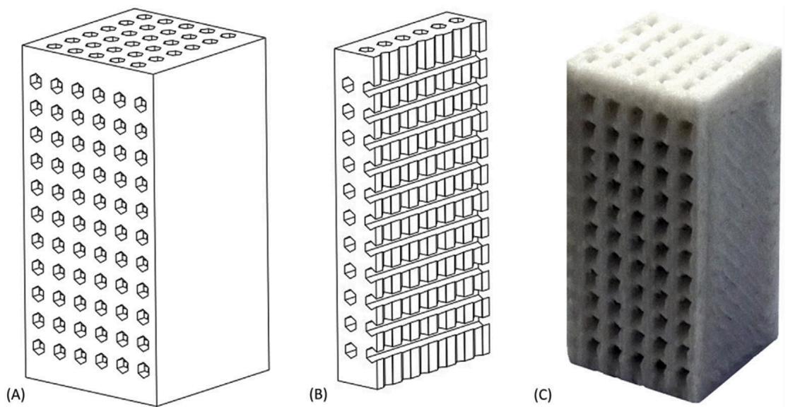
Fig. 10. Computer model (A), cut-away model (B) and 3D printed PLA/HA scaffold (C) [120].
where they have to withstand fluctuating loads, such as loaded skeleton sites [118,119]. It is critical that under cyclic loading, the biomaterial may experience fatigue, which tends to damage the material below its ultimate strength under static conditions, and in certain situations, failure may occur at a stress level below the material yield strength; both leading to the risk of human life. This emphasises the importance of fatigue analysis on biomedical materials. In this regard, Senatov et al. [120] investigated the fatigue strength of 3D printed PLA-based porous scaffolds. Two different scaffolds were printed with neat PLA and PLA with 15% of hydroxyapatite (HA). The printed PLA/HA scaffold is shown in Fig. 10. All the pores in the printed scaffolds were interconnected and the porosity measured was in the range of 30 vol%. In the fatigue test, the rate of deformation of the PLA scaffolds increased when the fatigue load increased, which tends to reduce the modulus. However, the introduction of HA into the PLA increased the PLA defective resistance, which resulted in increased resistance to crack formation leading to an increase in fatigue life. This is one of the first papers to evaluate the fatigue properties of the PLA-based scaffold produced by FDM. This result explicated the importance of introducing bioactive filler to increase the fatigue characteristics of the PLA. Analysis of the results increases the curiosity for understanding the fatigue nature of PLA with varying amounts of bioactive filler reinforcement.
In another study, Gong et al. [121] investigated the fatigue behaviour of 3D-printed scaffolds. Two types of PLA scaffolds were printed with a triangular and circular pore at a porosity of 60%. The scaffolds were exposed to a low-cycle compression type fatigue test at R = 0.5 and a frequency of 0.2 Hz. The authors found a significant variation in the fatigue life of the scaffolds with respect to the type of pore. The circular pore scaffold distributed the stress evenly, reducing the stress concentration, thus increasing the fatigue life. Nevertheless, the authors could have analysed fractured scaffolds with micro-images to observe the variation in the failure mechanism between the two scaffolds. Baptistaa and Guedes [122] analysed the fatigue fractured FDM printed PLA samples and reported shear fracture as the main degradation mechanism in the fatigue cyclic loading. It was interesting that no delamination or layer breakage occurred even after 3600 loading cycles. This was due to the strong bonding of the layer in the printed scaffold. These three investigations [120–122] of PLA scaffolds recommended 3D printed PLA material for bone repairing in biomedical applications. Miller et al. [123] studied the fatigue properties of FDM printed cross-linked polycarbonate urethane scaffolds. Fatigue strength analysis was performed with respect to the shape of the notch (circular and diamond notch). The authors observed an increase in fatigue life in the circular shape of the notch. The sharp corners of the diamond notch increased the stress concentration and reduced the fatigue life.
scatterplot
| Material | Density (kg/m³) | Compressive strength (MPa) |
|---|---|---|
| Graphen | ~2000 | ~100,000 |
| CNTs | ~2000 | ~100,000 |
| Diamond | ~2000 | ~100,000 |
| Carbon fiber epoxy | ~2000 | ~100,000 |
| Glassy carbon | ~200 | ~100 |
| Al₂O₃ lattices | ~300 | ~100 |
| Carbon lattices | ~200 | ~100 |
| Carbon | ~200 | ~100 |
| Glassy carbon lattices | ~200 | ~10 |
| CNT-aerogel | ~200 | ~10 |
| Graphite | ~200 | ~10 |
| Polymers | ~200 | ~10 |
| Bending-dominated behaviour | ~150 | ~50 |
| Carbon-lattice | ~150 | ~50 |
| Carbon | ~150 | ~150 |
| Carbon-honeycomb s | ~500 | ~1,000 |
| Carbon-lattice | ~150 | ~50 |
| CFP-R lattice | ~150 | ~50 |
| Glassy carbon lattices | ~150 | ~10 |
| Theoretical limit is shown as an orange line. A diagonal line labeled ‘Stretch-dominated behavior’ indicates a transition from stretch-dominated to stretch-dominated behavior. < | caption_end | > |
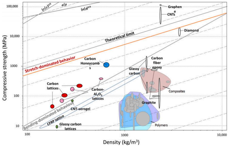
Fig. 11. Compressive strength–density diagram of different ACM and bulk materials [131].
4. Additive manufacturing enables architected cellular materials
The natural system is a result of ‘intelligent design’ perfected over a long period through evolution. Hence, modern technology uses replicas mimicking the natural design and structures. In the recent decades, one of the challenges in engineering materials is the production of lightweight materials with unparalleled multifunctional properties at low cost and with efficient use of materials and energy. As a result, human beings have produced several materials that are far superior to the natural materials available. Engineered materials possessing properties that are not usually found in naturally occurring materials are called meta-materials [124,125]. Meta-materials research is an interdisciplinary approach that has interconnected researchers from different disciplines. The properties of the meta-materials are achieved by tailoring the physical structure to make them unique. Bio inspired Architected Cellular Materials (ACMs) is one example, being the pioneers of lightweight-optimised materials with multiple functional properties such as high strength, stiffness, impact resistance, and damage tolerance, among others [126,127].
Cellular architectures are nature-produced structures that offer lightweight and enhanced mechanical strength, e.g. bird peaks and bones, which consist of porous cellular structure that makes it lighter and stronger [128]. Honeycomb structures, truss lattices, and foams are the typical examples of the well-established architected cellular structures. In ACMs, the honeycomb structure is the most popular design due to the increased energy absorption capacity that allows it to resist larger deformations [129]. ACMs are capable of resisting deformation exacerbated by bending and stretching dominant behaviour [130]. The mechanical properties of the architectural materials are influenced by the deformation mechanism involved (bend- or stretch-dominated). It is important to select optimised architecture to attain the desired properties. However, the cellular structure properties are influenced by three main factors such as bulk material property, the geometry of the cell structure, and the relative density [131]. The variation in the strength with respect to relative density can be understood from Fig. 11.
The geometry of ACM can be a man-made design that is generated by a complete process of engineering optimisation or bio-inspired. These materials have complex structures, which makes them difficult to manufacture using conventional methods. Years of technological research and development have made it possible to manufacture these materials with precise control over their properties. The advancement in commercial tools and technology has unlocked the way to the production of complex geometries of varying sizes and specifications for controlled properties, thus saving time and resources. The bottom-up technique is a well-suited manufacturing process instead of a materialremoving top-down approach that allows complex structures with internal features to be produced at multiple scales. AM is a wellestablished and versatile method that enables the production of these materials from the submicron to the centimetre scale. Valdevit et al. [132] listed 3D printing methods used for the printing of ACMs: stereolithography, projection microstereolithography (PμSL), continuous liquid interface printing, self-propagating polymer waveguides, twophoton polymerization (2PP), fused deposition modelling, polyjet, and powder-bed fusion.
4.1. Importance of fatigue evaluation in 3D printed polymer-based ACM
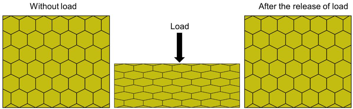
Cellular architected materials can replace lightweight materials due to their capability to possess high strength and stiffness. The development of 3D printing and design software enables optimisation of the cellular structure to achieve enhanced strength, stiffness, and energy absorption at reduced weight and density. 3D printing enables the development of ACMs at different architecture geometry. By tailoring the microstructure and geometry of architected materials, Muth et al. [133] achieved enhanced stiffness and the investigation performed different modes of deformation on varying architecture geometry. From the evidence that the variation in the architecture geometry could result in different modes of failure, it is understood that failure mechanism varies with respect to the type of base material used. By hybridising the design architecture strength, stiffness, and toughness can be increased, while further crack initiation, crack propagation and deformation can also be controlled [134]. In the available literature, only a few studies reported the failure of these materials under static and dynamic loading conditions. Fatigue behaviour of the FDM printed PLA material with a smooth hinge geometry design was investigated by Khare et al. [135]. The dynamic loading effect of the PLA with a smooth hinge geometry design was compared to the PLA with a honeycomb geometry. The smooth hinge geometry showed superior elastic behaviour, which recovered almost 96% of the strain after 35 cycles of loading, whereas for the honeycomb structure it was only 85%. This study explored the significance of the architecture geometry against the dynamic loading and by only considering two types of geometries. However, there is a dearth of research on polymer-based ACMs and further work is needed to comprehend the mechanical failure mechanisms in these novel materials. Fig. 12 shows the fatigue performance of ACM with honeycomb structure. Another important factor is the shortcomings in 3D printing i. e. formation of voids, poor interlayer adhesion and, sharp corners, which largely affect the material performance. In addition, the sharp corners in the architected material design can also lead to an increase in stress concentration [135]. In architected material, stress concentration promotes the initiation and propagation of fatigue damage [136]. Balancing fatigue life specifications with strength, stiffness and other desirable material properties is a serious challenge for the use of architected materials in applications where durability and reliability are crucial. It is necessary to investigate and optimise the geometry of the ACMs for static and dynamic loading, which will open the doors for the use of these materials in demanding applications.
text_image
Without load Load After the release of load
Fig. 12. Fatigue performance of ACM with honeycomb structure.
5. Conclusions and future prospects
This review article summarises the fundamental aspect of the fatigue behaviour of FDM printed polymeric materials. While FDM is a versatile manufacturing technique, it is not optimised or modified to ensure that polymeric materials are fully designed in accordance with the necessary mechanical requirements. Only a limited number of thermoplastic materials have been used in fatigue analysis of 3D printed products and studies on the fatigue behaviour of polymeric materials have not been sufficient. With these results, it is difficult to grasp the role of fatigue in FDM printed polymers and their composite materials. FDM-based fibre composites have better tensile and bending strength than neat polymers but the fatigue mechanism of these composites is not adequately reported. The fibre properties of FDM printed composites are expected to make a significant contribution to an increase in fatigue life. Biobased thermoplastic materials are found in various biomedical loadbearing applications such as scaffolds where fatigue life is critical. In the novel ACM, the fatigue properties should be examined in detail as the ACM has sharp corners and edges that increase the stress concentration at cyclic loading. There are still many challenges that need to be addressed in relation to particular material property and printing techniques. The following factors have been identified as crucial for increasing the fatigue life of FDM based polymeric materials;
• Printing parameters have a significant impact on fatigue behaviour that need to be optimised but studies related to the optimisation of printing parameters are rare. According to the available literature, the orientation of the raster angle of +45◦/− 45◦ yields a longer fatigue life in PLA and ABS-based printed materials.
• FDM uses different thermoplastic materials since the significant variation in their physical properties tends to change the fatigue nature. It is therefore suggested that FDM parameters should be optimised in relation to the material characteristics.
• Polymeric materials are viscoelastic and typical FDM and fatigue process involve varying temperatures. High environmental temperatures would reduce the fatigue life of polymeric materials.
• Defects and voids are common problems in FDM, which should be considered as factors in the optimisation of FDM since they increase the stress concentration.
• In polymeric fibre composites, fibre properties, fibre length, fibre loading percentage, fibre wettability are crucial for the determination of fatigue life. However, no results were found in the fatigue characteristics of FDM fibre composites.
• For ACM, along with the above-mentioned properties cellular geometry and bulk material properties are the key factors affecting the fatigue performance.
The data available for these factors are not sufficient to define, comprehend, or predict the fatigue mechanism of FDM-based polymeric material. Thus, research is encouraged on the subject that will facilitate the use of FDM-based materials in different engineering applications under different loading conditions.
Declaration of Competing Interest
The authors declare that they have no known competing financial interests or personal relationships that could have appeared to influence the work reported in this paper.
References
[1] Gebhardt A. Understanding additivemanufacturing. Carl Hanser Verlag GmbH & Co. KG; 2011. doi:10.3139/9783446431621.
[2] Dilberoglu UM, Gharehpapagh B, Yaman U, Dolen M. The role of additive manufacturing in the era of industry 4.0. Procedia Manuf 2017;11:545–54. https://doi.org/10.1016/j.promfg.2017.07.148.
[3] Harun WSW, Manam NS, Kamariah MSIN, Sharif S, Zulkifly AH, Ahmad I, et al. A review of powdered additive manufacturing techniques for Ti-6al-4v biomedical applications. Powder Technol 2018;331:74–97. https://doi.org/ 10.1016/j.powtec.2018.03.010.
[4] Delgado Camacho D, Clayton P, O’Brien WJ, Seepersad C, Juenger M, Ferron R, et al. Applications of additive manufacturing in the construction industry – a forward-looking review. Autom Constr 2018;89:110–9. https://doi.org/10.1016/ j.autcon.2017.12.031.
[5] Jyothish Kumar L, Krishnadas Nair CG. Current trends of additive manufacturing in the aerospace industry. In: Advances in 3D Printing and Additive Manufacturing Technologies, Springer Singapore; 2016: pp. 39–54. doi:10.1007/ 978-981-10-0812-2_4.
[6] Lipton JI, Cutler M, Nigl F, Cohen D, Lipson H. Additive manufacturing for the food industry. Trends Food Sci Technol 2015;43:114–23. https://doi.org/ 10.1016/j.tifs.2015.02.004.
[7] Lee JY, An J, Chua CK. Fundamentals and applications of 3D printing for novel materials. Appl Mater Today 2017;7:120–33. https://doi.org/10.1016/j. apmt.2017.02.004.
[8] Gibson I, Rosen D, Stucker B. In: Additive manufacturing technologies: 3D printing, rapid prototyping, and direct digital manufacturing. second ed. New York: Springer; 2015. https://doi.org/10.1007/978-1-4939-2113-3.
[9] Popescu D, Zapciu A, Amza C, Baciu F, Marinescu R. FDM process parameters influence over the mechanical properties of polymer specimens: a review. Polym Test 2018;69:157–66. https://doi.org/10.1016/j.polymertesting.2018.05.020.
[10] Mohamed OA, Masood SH, Bhowmik JL. Optimization of fused deposition modelling process parameters: a review of current research and future prospects. Adv Manuf 2015;3:42–53. https://doi.org/10.1007/s40436-014-0097-7.
[11] Liu Z, Wang Y, Wu B, Cui C, Guo Y, Yan C. A critical review of fused deposition modelling 3D printing technology in manufacturing polylactic acid parts. Int J Adv Manuf Technol 2019;102:2877–89. https://doi.org/10.1007/s00170-019- 03332-x.
[12] Tisserat B, Liu Z, Finkenstadt V, Lewandowski B, Ott S, Reifschneider L. 3D printing biocomposites. Plastic Res Online 2015;23:1–3. https://doi.org/ 10.2417/spepro.005690.
[13] Tao Y, Wang H, Li Z, Li P, Shi SQ. Development and application of wood flourfilled polylactic acid composite filament for 3D printing. Materials 2017;10:339. https://doi.org/10.3390/ma10040339.
[14] Kariz M, Sernek M, Obu´cina M, Kuzman MK. Effect of wood content in FDM filament on properties of 3D printed parts. Mater Today Commun 2018;14: 135–40. https://doi.org/10.1016/j.mtcomm.2017.12.016.
[15] Yang T-C. Effect of extrusion temperature on the physico-mechanical properties of unidirectional wood fiber-reinforced polylactic acid composite (WFRPC) components using fused deposition modelling. Polymers 2018;10:976. https:// doi.org/10.3390/polym10090976.
[16] Martikka Ossi, K¨arki Timo, Wu Qing Ling. Mechanical properties of 3D-printed wood-plastic composites. Key Eng Mater 2018;777:499–507 (accessed June 10, 2020), https://www.scientific.net/KEM.777.499.
[17] Zhang Q, Cai H, Zhang A, Lin X, Yi W, Zhang J. Effects of lubricant and toughening agent on the fluidity and toughness of poplar powder-reinforced polylactic acid 3D printing materials. Polymers 2018;10:932. https://doi.org/ 10.3390/polym10090932.
[18] Liu H, He H, Peng X, Huang B, Li J. Three-dimensional printing of poly(lactic acid) bio-based composites with sugarcane bagasse fiber: effect of printing orientation on tensile performance. Polym Adv Technol 2019;30:910–22. https:// doi.org/10.1002/pat.4524.
[19] Daver F, Lee KPM, Brandt M, Shanks R. Cork–PLA composite filaments for fused deposition modelling. Compos Sci Technol 2018;168:230–7. https://doi.org/ 10.1016/j.compscitech.2018.10.008.
[20] Stoof D, Pickering K, Zhang Y. Fused deposition modelling of natural fibre/ polylactic acid composites. J Compos Sci 2017;1:8. https://doi.org/10.3390/ jcs1010008.
[21] Ayrilmis N, Kariz M, Kwon JH, Kitek Kuzman M. Effect of printing layer thickness on water absorption and mechanical properties of 3D-printed wood/PLA composite materials. Int J Adv Manuf Technol 2019;102:2195–200. https://doi. org/10.1007/s00170-019-03299-9.
[22] Tao Y, Pan L, Liu D, Li P. A case study: mechanical modelling optimization of cellular structure fabricated using wood flour-filled polylactic acid composites with fused deposition modelling. Compos Struct 2019;216:360–5. https://doi. org/10.1016/j.compstruct.2019.03.010.
[23] Heidari-Rarani M, Rafiee-Afarani M, Zahedi AM. Mechanical characterization of FDM 3D printing of continuous carbon fiber reinforced PLA composites. Compos B Eng 2019;175:107147. https://doi.org/10.1016/j.compositesb.2019.107147.
[24] Yu S, Hwang YH, Hwang JY, Hong SH. Analytical study on the 3D-printed structure and mechanical properties of basalt fiber-reinforced PLA composites using X-ray microscopy. Compos Sci Technol 2019;175:18–27. https://doi.org/ 10.1016/j.compscitech.2019.03.005.
[25] Yang L, Li S, Zhou X, Liu J, Li Y, Yang M, et al. Effects of carbon nanotube on the thermal, mechanical, and electrical properties of PLA/CNT printed parts in the FDM process. Synth Met 2019;253:122–30. https://doi.org/10.1016/j. synthmet.2019.05.008.
[26] Luo J, Wang H, Zuo D, Ji A, Liu Y. Research on the application of MWCNTs/PLA composite material in the manufacturing of conductive composite products in 3D printing. Micromachines 2018;9:635. https://doi.org/10.3390/mi9120635.
[27] Moradi M, Karami Moghadam M, Shamsborhan M, Bodaghi M. The synergic effects of FDM 3D printing parameters on mechanical behaviors of bronze poly lactic acid composites, journal of composites. Science 2020;4:17. https://doi.org/ 10.3390/jcs4010017.
[28] Wang X, Jiang M, Zhou Z, Gou J, Hui D. 3D printing of polymer matrix composites: a review and prospective. Compos B Eng 2017;110:442–58. https:// doi.org/10.1016/j.compositesb.2016.11.034.
[29] Iqbal Mohammed M, Das A, Gomez-Kervin E, Wilson D, Gibson I. EcoPrinting: Investigating the use of 100% recycled Acrylonitrile Butadiene Styrene (ABS) for Additive Manufacturing. In: Proceedings of the 28th Annual International Solid Freeform Fabrication Symposium; 2017: pp. 532–542.
[30] Justo J, Tavara ´ L, García-Guzman ´ L, París F. Characterization of 3D printed long fibre reinforced composites. Compos Struct 2018;185:537–48. https://doi.org/ 10.1016/j.compstruct.2017.11.052.
[31] Parandoush P, Lin D. A review on additive manufacturing of polymer-fiber composites. Compos Struct 2017;182:36–53. https://doi.org/10.1016/j. compstruct.2017.08.088.
[32] Zhao Y, Chen Y, Zhou Y. Novel mechanical models of tensile strength and elastic property of FDM AM PLA materials: experimental and theoretical analyses. Mater Des 2019;181:108089. https://doi.org/10.1016/j.matdes.2019.108089.
[33] Mazzanti V, Malagutti L, Mollica F. FDM 3D printing of polymers containing natural fillers: a review of their mechanical properties. Polymers 2019;11:1094. https://doi.org/10.3390/polym11071094.
[34] Shofner ML, Lozano K, Rodríguez-Macías FJ, Barrera EV. Nanofiber-reinforced polymers prepared by fused deposition modelling. J Appl Polym Sci 2003;89: 3081–90. https://doi.org/10.1002/app.12496.
[35] Liao G, Li Z, Cheng Y, Xu D, Zhu D, Jiang S, et al. Properties of oriented carbon fiber/polyamide 12 composite parts fabricated by fused deposition modelling. Mater Des 2018;139:283–92. https://doi.org/10.1016/j.matdes.2017.11.027.
[36] Nikzad M, Masood SH, Sbarski I. Thermo-mechanical properties of a highly filled polymeric composites for Fused Deposition Modelling. Mater Des 2011;32: 3448–56. https://doi.org/10.1016/j.matdes.2011.01.056.
[37] Mohan N, Senthil P, Vinodh S, Jayanth N. A review on composite materials and process parameters optimisation for the fused deposition modelling process. Virtual Phys Prototyping 2017;12:47–59. https://doi.org/10.1080/ 17452759.2016.1274490.
[38] Yao SS, Jin FL, Rhee KY, Hui D, Park SJ. Recent advances in carbon-fiberreinforced thermoplastic composites: a review. Compos B Eng 2018;142:241–50. https://doi.org/10.1016/j.compositesb.2017.12.007.
[39] Suhr J, Victor P, Ci L, Sreekala S, Zhang X, Nalamasu O, et al. Fatigue resistance of aligned carbon nanotube arrays under cyclic compression. Nat Nanotechnol 2007;2:417–21. https://doi.org/10.1038/nnano.2007.186.
[40] Cui T, Mukherjee S, Sudeep PM, Colas G, Najafi F, Tam J, et al. Fatigue of graphene. Nat Mater 2020;19:405–11. https://doi.org/10.1038/s41563-019- 0586-y.
[41] Polymer Solids and Polymer Melts–Mechanical and Thermomechanical Properties of Polymers, Springer Berlin Heidelberg, 2014. doi:10.1007/978-3-642-55166-6.
[42] Kelly Anthony, Zweben Carl. Comprehensive Composite Materials, Science Direct; 2000. https://www.sciencedirect.com/referencework/97800804 29939/comprehensive-composite-materials (accessed August 10, 2020).
[43] Ralph HOF, Stephens I, Fatemi Ali, Stephens Robert R. Metal Fatigue in Engineering, (n.d.).
[44] Fuchs HO, Stephens RI, Saunders H. Metal Fatigue in Engineering (1980). J Eng Mater Technol 1981;103:346. https://doi.org/10.1115/1.3225026.
[45] Schijve J. Fatigue of structures and materials in the 20th century and the state of the art. Int J Fatigue 2003;25:679–702. https://doi.org/10.1016/S0142-1123 (03)00051-3.
[46] Moore JP, Williams CB. Fatigue properties of parts printed by PolyJet material jetting. Rapid Prototyping J 2015;21:675–85. https://doi.org/10.1108/RPJ-03- 2014-0031.
[47] Riddell MN, Koo GP, O’Toole JL. Fatigue mechanisms of thermoplastics. Polym Eng Sci 1966;6:363–8. https://doi.org/10.1002/pen.760060414.
[48] Safai L, Cuellar JS, Smit G, Zadpoor AA. A review of the fatigue behavior of 3D printed polymers. Addit Manuf 2019;28:87–97. https://doi.org/10.1016/j. addma.2019.03.023.
[49] Chandran KSR. Mechanical fatigue of polymers: A new approach to characterize the S-N behavior on the basis of macroscopic crack growth mechanism. Polymer 2016;91:222–38. https://doi.org/10.1016/j.polymer.2016.03.058.
[50] Pruitt LA, Rama Sreekanth PS, Badgayan ND, Sahoo SK. Fatigue of Polymers. In: Reference Module in Materials Science and Materials Engineering. Elsevier; 2017. https://doi.org/10.1016/b978-0-12-803581-8.00904-8.
[51] Mortazavian S, Fatemi A. Fatigue behavior and modelling of short fiber reinforced polymer composites: a literature review. Int J Fatigue 2015;70: 297–321. https://doi.org/10.1016/j.ijfatigue.2014.10.005.
[52] Ansari MTA, Singh KK, Azam MS. Fatigue damage analysis of fiber-reinforced polymer composites—A review. J Reinf Plast Compos 2018;37:636–54. https:// doi.org/10.1177/0731684418754713.
[53] Crawford R, Martin P. Plastics engineering; 2020. https://books.google.com/boo ks?hl=en&lr=&id=aci2DwAAQBAJ&oi=fnd&pg=PP1&ots=d_AeUm FRgb&sig=D7vd3wzqiP_CtaH7WJ9h8anteOw (accessed August 10, 2020).
[54] Amjadi M, Fatemi A. Multiaxial fatigue behavior of thermoplastics including mean stress and notch effects: experiments and modelling. Int J Fatigue 2020; 136:105571. https://doi.org/10.1016/j.ijfatigue.2020.105571.
[55] Sauer JA, Richardson GC. Fatigue of polymers. Int J Fract 1980;16:499–532. https://doi.org/10.1007/BF02265215.
[56] Delamination-dominated failures in polymer composites. In: Failure Analysis and Fractography of Polymer Composites, Elsevier; 2009: pp. 164–237. doi:10.1533 /9781845696818.164.
[57] Hughes JM, Lugo M, Bouvard JL, McIntyre T, Horstemeyer MF. Cyclic behavior and modelling of small fatigue cracks of a polycarbonate polymer. Int J Fatigue 2017;99:78–86. https://doi.org/10.1016/j.ijfatigue.2016.12.012.
[58] Matsuda S, Ogi K. A stochastic approach for continuous and discontinuous crack growth in polycarbonate under cyclic loading. Polym Eng Sci 2013;53:1920–6. https://doi.org/10.1002/pen.23457.
[59] Akano TT, Fakinlede OA. Fatigue failure model for polymeric compliant systems. ISRN Polymer Science 2013;2013:321489. https://doi.org/10.1155/2013/ 321489.
[60] Tanaka K, Kitano T, Egami N. Effect of fiber orientation on fatigue crack propagation in short-fiber reinforced plastics. Eng Fract Mech 2014;123:44–58. https://doi.org/10.1016/j.engfracmech.2014.03.019.
[61] Wicaksono S, Chai GB. A review of advances in fatigue and life prediction of fiberreinforced composites. Proce Inst Mech Eng Part L: J Mater Des Appl 2013;227: 179–95. https://doi.org/10.1177/1464420712458201.
[62] Szeb´enyi G, Magyar B, Iv´anyicki T. Comparison of static and fatigue interlaminar testing methods for continuous fiber reinforced polymer composites. Polym Test 2017;63:307–13. https://doi.org/10.1016/j.polymertesting.2017.08.033.
[63] Shrestha R, Simsiriwong J, Shamsaei N, Moser RD. Cyclic deformation and fatigue behavior of polyether ether ketone (PEEK). Int J Fatigue 2016;82:411–27. https://doi.org/10.1016/j.ijfatigue.2015.08.022.
[64] Fargione G, Geraci A, La Rosa G, Risitano A. Rapid determination of the fatigue curve by the thermographic method. Int J Fatigue 2002;24:11–9. https://doi.org/ 10.1016/S0142-1123(01)00107-4.
[65] La Rosa G, Risitano A. Thermographic methodology for rapid determination of the fatigue limit of materials and mechanical components. Int J Fatigue 2000;22: 65–73. https://doi.org/10.1016/S0142-1123(99)00088-2.
[66] Santonocito D. Evaluation of fatigue properties of 3D-printed Polyamide-12 by means of energy approach during tensile tests. Procedia Struct Integrity 2020;25: 355–63. https://doi.org/10.1016/j.prostr.2020.04.040.
[67] Frascio M, Avalle M, Monti M. Fatigue strength of plastics components made in additive manufacturing: First experimental results. In: Procedia Structural Integrity, Elsevier B.V.; 2018: pp. 32–43. doi:10.1016/j.prostr.2018.11.109.
[68] El Magri A, El Mabrouk K, Vaudreuil S, Ebn Touhami M. Mechanical properties of CF-reinforced PLA parts manufactured by fused deposition modelling. J Thermoplastic Compos Mater 2019. https://doi.org/10.1177/ 0892705719847244. 089270571984724.
[69] Rahim TNAT, Abdullah AM, Md Akil H. Recent developments in fused deposition modelling-based 3D printing of polymers and their composites. Polym Rev 2019; 59:589–624. https://doi.org/10.1080/15583724.2019.1597883.
[70] Wang S, Ma Y, Deng Z, Zhang S, Cai J. Effects of fused deposition modelling process parameters on tensile, dynamic mechanical properties of 3D printed polylactic acid materials. Polym Test 2020;86:106483. https://doi.org/10.1016/ j.polymertesting.2020.106483.
[71] Ahn SH, Montero M, Odell D, Roundy S, Wright PK. Anisotropic material properties of fused deposition modelling ABS. Rapid Prototyping J 2002;8: 248–57. https://doi.org/10.1108/13552540210441166.
[72] Ezeh OH, Susmel L. Fatigue strength of additively manufactured polylactide (PLA): effect of raster angle and non-zero mean stresses. Int J Fatigue 2019;126: 319–26. https://doi.org/10.1016/j.ijfatigue.2019.05.014.
[73] Ezeh OH, Susmel L. On the fatigue strength of 3D-printed polylactide (PLA). In: Procedia Structural Integrity, Elsevier B.V.; 2018: pp. 29–36. doi:10.1016/j. prostr.2018.06.007.
[74] Jerez-Mesa R, Travieso-Rodriguez JA, Llum`a-Fuentes J, Gomez-Gras G, Puig D. Fatigue lifespan study of PLA parts obtained by additive manufacturing. Procedia Manuf 2017;13:872–9. https://doi.org/10.1016/j.promfg.2017.09.146.
[75] Gomez-Gras G, Jerez-Mesa R, Travieso-Rodriguez JA, Lluma-Fuentes J. Fatigue performance of fused filament fabrication PLA specimens. Mater Des 2018;140: 278–85. https://doi.org/10.1016/j.matdes.2017.11.072.
[76] Afrose MF, Masood SH, Iovenitti P, Nikzad M, Sbarski I. Effects of part build orientations on fatigue behaviour of FDM-processed PLA material. Progr Additive Manuf 2016;1:21–8. https://doi.org/10.1007/s40964-015-0002-3.
[77] Letcher T, Waytashek Megan. Material Property Testing of 3D-Printed Specimen in PLA on an Entry-Level 3D Printer Cellular Metamaterials View project Linking an Energy-Based Fatigue Life Prediction to Fracture Mechanics View project. In: Proceedings of the ASME 2014 International Mechanical Engineering Congress & Exposition, ASME, Montreal, Quebec, Canada, 2014. doi:10.1115/IMECE201 4-39379.
[78] Arbeiter F, Spoerk M, Wiener J, Gosch A, Pinter G. Fracture mechanical characterization and lifetime estimation of near-homogeneous components produced by fused filament fabrication. Polym Test 2018;66:105–13. https://doi. org/10.1016/j.polymertesting.2018.01.002.
[79] Ezeh OH, Susmel L. On the notch fatigue strength of additively manufactured polylactide (PLA). Int J Fatigue 2020;136:105583. https://doi.org/10.1016/j. ijfatigue.2020.105583.
[80] Zhang H, Cai L, Golub M, Zhang Y, Yang X, Schlarman K, et al. Tensile, creep, and fatigue behaviors of 3D-printed acrylonitrile butadiene styrene. J Mater Eng Perform 2018;27:57–62. https://doi.org/10.1007/s11665-017-2961-7.
[81] Ziemian S, Okwara M, Ziemian CW. Tensile and fatigue behavior of layered acrylonitrile butadiene styrene. Rapid Prototyping J 2015;21:270–8. https://doi. org/10.1108/RPJ-09-2013-0086.
[82] Jap NSF, Pearce GM, Hellier AK, Russell N, Parr WC, Walsh WR. The effect of raster orientation on the static and fatigue properties of filament deposited ABS
polymer. Int J Fatigue 2019;124:328–37. https://doi.org/10.1016/j. ijfatigue.2019.02.042.
[83] Lampman S. Characterization and failure analysis of plastics; 2003. https://boo ks.google.com/books?hl=en&lr=&id=RJWiilJLdxYC&oi=fnd&pg=PA1&ots=L 3T-hLHwkR&sig=pXUgPzUDAkN90ny9Ehr_2QZdS54 (accessed August 11, 2020).
[84] Domingo-Espin M, Travieso-Rodriguez JA, Jerez-Mesa R, Lluma-Fuentes J. Fatigue performance of ABS specimens obtained by fused filament fabrication. Materials 2018;11:2521. https://doi.org/10.3390/ma11122521.
[85] Lee J, Huang A. Fatigue analysis of FDM materials. Rapid Prototyping J 2013;19: 291–9. https://doi.org/10.1108/13552541311323290.
[86] Corbett Taylor, Kok Thijs, Lee ChaBum, Smith Stuart T, Villarraga Herminso, Tarbutton Joshua A. Identification of mechanical and fatigue characteristics of polymers fabricated by additive manufacturing process. ASPE Spring Topical Meeting 2014;57:186–9 (accessed August 12, 2020), https://www.researchgate. net/publication/283119165.
[87] Padzi MM, Bazin MM, Muhamad WMW. In: Fatigue Characteristics of 3D Printed Acrylonitrile Butadiene Styrene (ABS). Institute of Physics Publishing; 2017. p. 012060. https://doi.org/10.1088/1757-899X/269/1/012060.
[88] Ziemian CW, Ziemian RD, Haile KV. Characterization of stiffness degradation caused by fatigue damage of additive manufactured parts. Mater Des 2016;109: 209–18. https://doi.org/10.1016/j.matdes.2016.07.080.
[89] Mishra SB, Mahapatra SS. An experimental investigation on strain controlled fatigue behaviour of FDM build parts. Int J Prod Quality Manage 2018;24: 323–45. https://doi.org/10.1504/IJPQM.2018.092980.
[90] Dolzyk G, Jung S. Tensile and fatigue analysis of 3D-printed polyethylene terephthalate glycol. J Fail Anal Prev 2019;19:511–8. https://doi.org/10.1007/ s11668-019-00631-z.
[91] Terekhina S, Tarasova T, Egorov S, Skornyakov I, Guillaumat L, Hattali ML. The effect of build orientation on both flexural quasi-static and fatigue behaviours of filament deposited PA6 polymer. Int J Fatigue 2020;140:105825. https://doi.org/ 10.1016/j.ijfatigue.2020.105825.
[92] Terekhina S, Tarasova T, Egorov S, Guillaumat L, Hattali ML. On the difference in material structure and fatigue properties of polyamide specimens produced by fused filament fabrication and selective laser sintering. Int J Adv Manuf Technol 2020;111:93–107. https://doi.org/10.1007/s00170-020-06026-x.
[93] Puigoriol-Forcada JM, Alsina A, Salazar-Martín AG, Gomez-Gras G, P´erez MA. Flexural fatigue properties of polycarbonate fused-deposition modelling specimens. Mater Des 2018;155:414–21. https://doi.org/10.1016/j. matdes.2018.06.018.
[94] Miller AT, Safranski DL, Smith KE, Sycks DG, Guldberg RE, Gall K. Fatigue of injection molded and 3D printed polycarbonate urethane in solution. Polymer 2017;108:121–34. https://doi.org/10.1016/j.polymer.2016.11.055.
[95] Fischer M, Schoppner ¨ V. Fatigue behavior of FDM parts manufactured with Ultem 9085. JOM. 2017;69:563–8. https://doi.org/10.1007/s11837-016-2197-2.
[96] Zhu J, Hu Y, Tang Y, Wang B. Effects of styrene-acrylonitrile contents on the properties of ABS/SAN blends for fused deposition modelling. J Appl Polym Sci 2017;134. https://doi.org/10.1002/app.44477.
[97] Wang J, Zhang Y, Sun W, Chu S, Chen T, Sun A, et al. Morphology evolutions and mechanical properties of in situ fibrillar polylactic acid/thermoplastic polyurethane blends fabricated by fused deposition modelling. Macromol Mater Eng 2019;304:1900107. https://doi.org/10.1002/mame.201900107.
[98] Singh R, Kumar R, Ahuja IPS. Mechanical, thermal and melt flow of aluminumreinforced PA6/ABS blend feedstock filament for fused deposition modelling. Rapid Prototyping J 2018;24:1455–68. https://doi.org/10.1108/RPJ-05-2017- 0094.
[99] Stepashkin DI, Chukov FS, Senatov AI, Salimon AM, Korsunsky SD. Kaloshkin, 3D-printed PEEK-carbon fiber (CF) composites: structure and thermal properties. Compos Sci Technol 2018;164:319–26. https://doi.org/10.1016/j. compscitech.2018.05.032.
[100] Vaezi M, Yang S. Extrusion-based additive manufacturing of PEEK for biomedical applications. Virtual Phys Prototyping 2015;10:123–35. https://doi.org/ 10.1080/17452759.2015.1097053.
[101] Wu W, Geng P, Li G, Zhao D, Zhang H, Zhao J. Influence of layer thickness and raster angle on the mechanical properties of 3D-printed PEEK and a comparative mechanical study between PEEK and ABS. Materials 2015;8:5834–46. https:// doi.org/10.3390/ma8095271.
[102] Pertuz AD, Díaz-Cardona S, Gonz´alez-Estrada OA. Static and fatigue behaviour of continuous fibre reinforced thermoplastic composites manufactured by fused deposition modelling technique. Int J Fatigue 2020;130:105275. https://doi.org/ 10.1016/j.ijfatigue.2019.105275.
[103] Travieso-Rodriguez JA, Zandi MD, Jerez-Mesa R, Lluma-Fuentes J. Fatigue behavior of PLA-wood composite manufactured by fused filament fabrication. J Mater Res Technol 2020;9:8507–16. https://doi.org/10.1016/j. jmrt.2020.06.003.
[104] Brooks H, Tyas D, Molony S. Tensile and fatigue failure of 3D printed parts with continuous fibre reinforcement. Int J Rapid Manuf 2017;6:97. https://doi.org/ 10.1504/ijrapidm.2017.082152.
[105] Essassi K, luc Rebiere J, El Mahi A, Ben Souf MA, Bouguecha A, Haddar M. Experimental and analytical investigation of the bending behaviour of 3D-printed bio-based sandwich structures composites with auxetic core under cyclic fatigue tests. Compos Part A: Appl Sci Manuf 2020;131. https://doi.org/10.1016/j. compositesa.2020.105775.
[106] Kabir SMF, Mathur K, Seyam AFM. A critical review on 3D printed continuous fiber-reinforced composites: history, mechanism, materials and properties.
Compos Struct 2020;232:111476. https://doi.org/10.1016/j. compstruct.2019.111476.
[107] Tian X, Liu T, Yang C, Wang Q, Li D. Interface and performance of 3D printed continuous carbon fiber reinforced PLA composites. Compos A Appl Sci Manuf 2016;88:198–205. https://doi.org/10.1016/j.compositesa.2016.05.032.
[108] Komatsu S, Takahara A, Kajiyama T. Effect of cyclic fatigue conditions on nonlinear dynamic viscoelasticity and fatigue behaviors for short glass-fiber reinforced nylon6. Polym J 2003;35:844–50. https://doi.org/10.1295/ polymj.35.844.
[109] Zhao X, Wang X, Wu Z, Zhu Z. Fatigue behavior and failure mechanism of basalt FRP composites under long-term cyclic loads. Int J Fatigue 2016;88:58–67. https://doi.org/10.1016/j.ijfatigue.2016.03.004.
[110] Ziemian C, Sharma M, Ziemi S. Anisotropic mechanical properties of ABS parts fabricated by fused deposition modelling. In: Mechanical Engineering, InTech; 2012. doi:10.5772/34233.
[111] Ziemian CW, Cipoletti DE, Ziemian SN, Okwara MN, Haile KV. Monotonic and cyclic tensile properties of ABS components fabricated by Addit Manuf 2014.
[112] Mohammadizadeh M, Imeri A, Fidan I, Elkelany M. 3D printed fiber reinforced polymer composites - structural analysis. Compos B Eng 2019;175:107112. https://doi.org/10.1016/j.compositesb.2019.107112.
[113] Ni J, Ling H, Zhang S, Wang Z, Peng Z, Benyshek C, et al. Three-dimensional printing of metals for biomedical applications. Mater. Today Bio. 2019;3:100024. https://doi.org/10.1016/j.mtbio.2019.100024.
[114] Yan Q, Dong H, Su J, Han J, Song B, Wei Q, et al. A review of 3D printing technology for medical applications. Engineering 2018;4:729–42. https://doi. org/10.1016/j.eng.2018.07.021.
[115] Derby B. Printing and prototyping of tissues and scaffolds. Science 2012;338: 921–6. https://doi.org/10.1126/science.1226340.
[116] Choong YYC, Tan HW, Patel DC, Choong WTN, Chen C-H, Low HY, et al. The global rise of 3D printing during the COVID-19 pandemic. Nat Rev Mater 2020: 1–3. https://doi.org/10.1038/s41578-020-00234-3.
[117] Gao M, Zhang H, Dong W, Bai J, Gao B, Xia D, et al. Tissue-engineered trachea from a 3D-printed scaffold enhances whole-segment tracheal repair. Sci Rep 2017;7:1–12. https://doi.org/10.1038/s41598-017-05518-3.
[118] Bose S, Vahabzadeh S, Bandyopadhyay A. Bone tissue engineering using 3D printing. Mater Today 2013;16:496–504. https://doi.org/10.1016/j. mattod.2013.11.017.
[119] Ma H, Li T, Huan Z, Zhang M, Yang Z, Wang J, et al. 3D printing of high-strength bioscaffolds for the synergistic treatment of bone cancer. NPG Asia Mater 2018; 10:31–44. https://doi.org/10.1038/s41427-018-0015-8.
[120] Senatov FS, Niaza KV, Stepashkin AA, Kaloshkin SD. Low-cycle fatigue behavior of 3d-printed PLA-based porous scaffolds. Compos B Eng 2016;97:193–200. https://doi.org/10.1016/j.compositesb.2016.04.067.
[121] Gong B, Cui S, Zhao Y, Sun Y, Ding Q. Strain-controlled fatigue behaviors of porous PLA-based scaffolds by 3D-printing technology. J Biomater Sci Polym Ed 2017;28:2196–204. https://doi.org/10.1080/09205063.2017.1388993.
[122] Baptista R, Guedes M. Fatigue behavior of different geometry scaffolds for bone replacement. In: Procedia Structural Integrity, Elsevier B.V.; 2019: pp. 539–546. doi:10.1016/j.prostr.2019.08.072.
[123] Miller AT, Safranski DL, Wood C, Guldberg RE, Gall K. Deformation and fatigue of tough 3D printed elastomer scaffolds processed by fused deposition modelling and continuous liquid interface production. J Mech Behav Biomed Mater 2017; 75:1–13. https://doi.org/10.1016/j.jmbbm.2017.06.038.
[124] Bertoldi K, Vitelli V, Christensen J, Van Hecke M. Flexible mechanical metamaterials. Nat Rev Mater 2017;2:1–11. https://doi.org/10.1038/ natrevmats.2017.66.
[125] Borja AL, Kelly JR, Zhang F, Lheurette E. Metamaterials. Int J Antennas Propagation 2013;2013. https://doi.org/10.1155/2013/516939.
[126] Tancogne-Dejean T, Spierings AB, Mohr D. Additively-manufactured metallic micro-lattice materials for high specific energy absorption under static and dynamic loading. Acta Mater 2016;116:14–28. https://doi.org/10.1016/j. actamat.2016.05.054.
[127] Al-Ketan O, Rowshan R, Abu Al-Rub RK. Topology-mechanical property relationship of 3D printed strut, skeletal, and sheet based periodic metallic cellular materials. Addit Manuf 2018;19:167–83. https://doi.org/10.1016/j. addma.2017.12.006.
[128] Schaedler TA, Carter WB. Architected cellular materials. Annu Rev Mater Res 2016;46:187–210. https://doi.org/10.1146/annurev-matsci-070115-031624.
[129] Zhang Q, Yang X, Li P, Huang G, Feng S, Shen C, et al. Bioinspired engineering of honeycomb structure - Using nature to inspire human innovation. Prog Mater Sci 2015;74:332–400. https://doi.org/10.1016/j.pmatsci.2015.05.001.
[130] Khaderi SN, Deshpande VS, Fleck NA. The stiffness and strength of the gyroid lattice. Int J Solids Struct 2014;51:3866–77. https://doi.org/10.1016/j. ijsolstr.2014.06.024.
[131] Kaur M, Han SM, Kim WS. Three-dimensionally printed cellular architecture materials: perspectives on fabrication, material advances, and applications. MRS Commun 2016;7:8–19. https://doi.org/10.1557/mrc.2016.62.
[132] Valdevit L, Bertoldi K, Guest J, Spadaccini C. Architected materials: synthesis, characterization, modelling, and optimal design. J Mater Res 2018;33:241–6. https://doi.org/10.1557/jmr.2018.18.
[133] Muth JT, Dixon PG, Woish L, Gibson LJ, Lewis JA. Architected cellular ceramics with tailored stiffness via direct foam writing. PNAS 2017;114:1832–7. https:// doi.org/10.1073/pnas.1616769114.
[134] Jia Z, Yu Y, Hou S, Wang L. Biomimetic architected materials with improved dynamic performance. J Mech Phys Solids 2019;125:178–97. https://doi.org/ 10.1016/j.jmps.2018.12.015.
[135] Khare E, Temple S, Tomov I, Zhang F, Smoukov SK. Low fatigue dynamic auxetic lattices with 3D printable, multistable, and tuneable unit cells. Front. Mater. 2018;5:45. https://doi.org/10.3389/fmats.2018.00045.
[136] Torres AM, Trikanad AA, Aubin CA, Lambers FM, Luna M, Rimnac CM, et al. Bone-inspired microarchitectures achieve enhanced fatigue life. PNAS 2019;116: 24457–62. https://doi.org/10.1073/pnas.1905814116.